|
Introduction: My First Yagi, Log-Periodic Array and
my Tri-Band Wire Yagi
As a Ham Radio Operator, antennas have always been of interest to me. I have
used many different antenna types over the years, DIPOLES, QUADS and
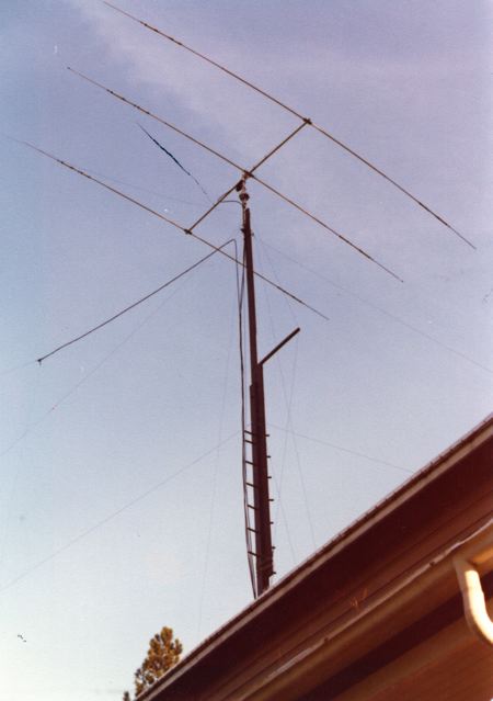
VERTICALS, but my first Yagi, an old TA-3 Tri-bander mounted on a home made
tilt over wood tower on top of my home was a real eye opener.
My First Tri-Band Yagi
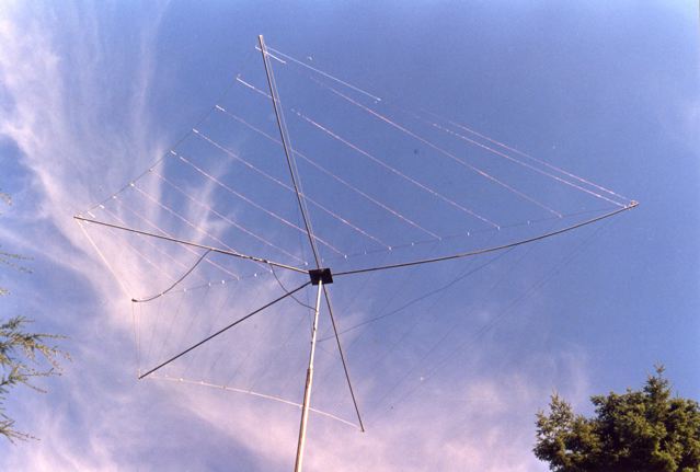
When we moved to North Vancouver, I decided to build a
wire Log Period Dipole Arry, (LPDA) called the Telerana which is pictured below and also featured in the
LPDA menu heading above.
My First Log-Periodic Array
A Tri-Band 2 Element Portable Yagi
After operating QRP/portable during the 1996 ARRL Sweepstakes Contest I decided
that the next time I entered a QRP contest it was going to be with an antenna
that had gain over the dipole antennas I was using! Operating from a
temporary location, a tower and tri-band yagi
constructed of aluminum tubing was not an option. After much thought and a
lot of reading, I decided to build a tri-band 2 element yagi
using wire elenments. The results of this
experiment are contained in an article published in the November 2001 issue
of QST. A PDF file of the article as well as the EZNEC antenna files is
available at the following links.
Portable 3-Band Wire Yagi Article
EZNEC Triband File at
30 Feet.
(Copyright ARRL. All rights reserved, used with permission of the ARRL.)
Additional Construction Notes:
WARC Bands
Many have requested information regarding adding the WARC bands. This is very
difficult as the 17 and 12 meter bands are very close to the 20, 15 and 10
meter bands and because of interaction between the elements I was not able to
obtain a satisfactory SWR on all bands. Click on More-Yagis
in the menu bar above for my WARC band portable yagi
design.
Assembly
When you are ready to assemble the array, attach the 20 meter reflector and
the driven elements first and then hang the array between two supports,
(trees etc.) at about 5 feet above the ground. Pull it tight so that the
array is fairly flat. It won’t stay flat
because the driven elements are heavier than the 20 meter reflector so
support one end of the 2 x 2 end supports on a rung of a step ladder or box
so that the array lies horizontal. Add the 10 and 15 meter reflectors next
using a little less tension than the 20 reflector. Next attach the feed line.
The last step is to adjust the V slings as mentioned below so that the
antenna is balanced in the horizontal plane. All adjustment for lowest SWR,
if needed, must be done with the antenna raised to its typical operating
position. Do not attempt to adjust any of the element lengths or the hair-pin
match for lower SWR while the array is close to the ground. Check the SWR on
each band with the antenna at a height of at least 25 feet before attempting
any adjustments.
V Slings
There are two V slings, one on each end. The secret is that they are not
equilateral in shape. The combined weight of the driven elements and feed
line is heavier than the reflectors. If the length of the sides of the V
sling are equal, the array will turn with the 2 x 2 end supports positioned
vertically. Increasing the tension on the side of the V that is attached to
the end where the driven elements are attached causes the whole array to turn
toward the horizontal plane. Do this by shortening the length of the side of
the V that is attached to the driven elements. It is quite easy to adjust in
the field. Once the V sling is adjusted, the array stays balanced. You can
change direction 180 degrees by pulling on the the
feed-line. If you pull it hard enough, the whole array will begin to
turn-flip over. Stop it from turning too far by holding on to the feed line
once the array has swung over to face the opposite direction.
Balun
It is not clear what to do with the coil of coax at the feed point in Fig. 1.
This is meant to be a choke balun to choke off any
RF from flowing along the outside of the coax shield. It is best to let the
coax feed line drop straight down from the centre
insulator, attach it to the centre of the hair-pin
shorting bar with a plastic tie or string and then make the balun by coiling up the coax 6 to 8 turns with a diameter
of 4 inches or so just below this point. The centre
of the shorting bar is neutral potential so there is no problem mechanically
attaching the feed line to it for support.
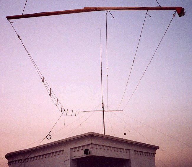
Here is a photo of KX7YT's
rendition of the portable tri-band yagi taken
while John was operating portable in Afghansitan as
YA/KX7YT.
November 17, 2009 update.
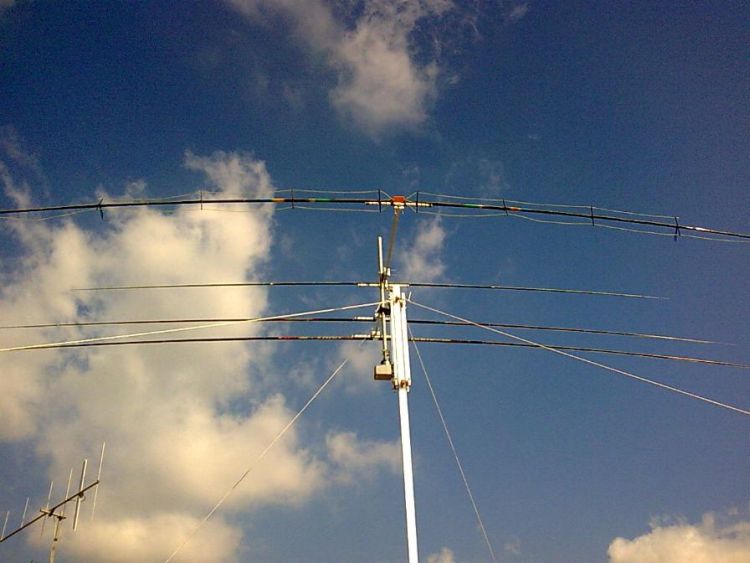
Mimmo, IZ0GIF recently sent the following email:
Hi Markus, I am Mimmo IZ0GIF from Italy. I would
like to thank you for your portable yagi project
that I transformed in rotatable yagi. I used
fiberglass fishing poles like supports, an alluminium
tube for the boom. SWR is less then 1.4 on all bands, it weights only 6 Kg
and reports are very good from USA and Middle East. With a cost of about 60
Euros I think it is the cheapest rotatable yagi I
have ever seen, HI. Thank you again and best 73 de IZ0GIF - Mimmo.
You may contact Mimmo via his email address at:
[email protected] for further details.
Here is a photo of of IZ0GIF's antenna clearly showing his construction
method.
There are hundreds of these antennas being used in countries all over the world
since the orginal article was published in November
2001 issue of QST and in the ARRL ANTENNA HANDBOOK since 2002.
|