IN3OTD's web site
...under perpetual construction.

Caddock MP9100-series resistor measurements
Under construction...
The non-inductive resistors made by Caddock are sometimes used to build an inexpensive dummy load, also because they are readily available from the usual distributors and use an easy to mount package (TO-247 or TO-220 for the lower power versions).
As I needed a small dummy load for testing some low power amplifiers, mainly for the HF bands, I was curious to understand how "non-inductive" these resistors actually were. I selected the higher power model, the MP9100 series, which is available in the TO-247 package and has a ceramic mounting surface on the back, so that an additional insulating thermal pad is not necessary; this helps in keeping the thermal resistance from the resistive element to the heat sink to a minimum.
To characterize the resistor behavior, I mounted it over the bare copper ground plane of an unetched PCB and used a large binder clip to hold it in place; this allows for some interesting experiments, described later. The two resistor terminals were soldered to two SMA connectors near the resistor body, just at the point where the terminals become narrower, to reduce the parasitics inductance due to the connections. This arrangement was then characterized with a VNA, of course after a proper calibration.
All the measurements results shown below were preprocessed to remove the effects of the SMA connectors (i.e. the connectors were de-embedded), so that the reference plane for the data is right at the resistor terminals. Of course the effect of the connectors is small, so the de-embedding has only a limited effect,
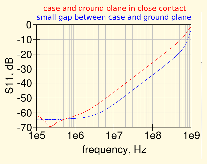
The graph below shows the measured return loss for a MP9100 50 ohm resistor


