THE AR88 RECEIVER
The AR88 has a special place for myself and many other experienced British amateurs. Part of the reason was availability after the war. A large number of these were shipped over and later they appeared on the market. I have been told the story that, at the beginning of the war all amateur equipment was confiscated, and the receivers pushed into military service. At the war's end, these had become dispersed and destroyed ,and as replacements a number of amateurs were rewarded with brand new AR88's. My section in the RAF used a number of AR88's, and it was my good fortune to be responsible for repairing them. I still have the SWL logs from those days - when I should have been working!
The illustrations here were taken from a handbook, thus they are not of high quality.
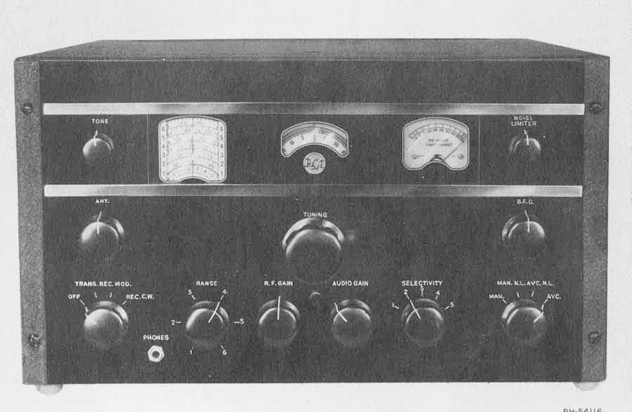
As is obvious from the other pages, I an a fervent fan of Collins equipment. However I have not personally come across any piece of equipment other than the AR88, which was made to such battleship standards - the handbook says it weighs 100 pounds - unpacked of course!!!
There were two basic models, the AR88D and the AR88LF. The "D" covered 535 KHz - 32 MHz in 6 bands. The LF covered 73-550KHz and 1480-30.5MHz also in 6 bands. Having the medium wave band, the "D" was rather more popular, but with today's VLF allocations, the "LF" would indeed come into it's own!
From now on it gets a bit technical, if you are an enthusiast read on ......... If not, well have a look at the Collins equipment.
No expense seems to have been spared in the design, for instance - the tuning knob is attached to a hefty gear assembly in which there are three large gears and a number of smaller ones. To avoid backlash the large gears are split vertically and each half spring loaded against the other, causing them to grip the smaller ones. I would bet that this gear system alone, in today's money, would cost many hundreds of pounds. It drove two dials and what was effectively an 8-gang variable capacitor. The delightful feel of the tuning was enhanced by the presence of a large and heavy flywheel. This dial could really be spun, and the repeatability of the frequency readings was legendary. Finally, and I am sure that all who remember it will agree, that spinning the dial was accompanied by a satisfying rumble of gears from within!
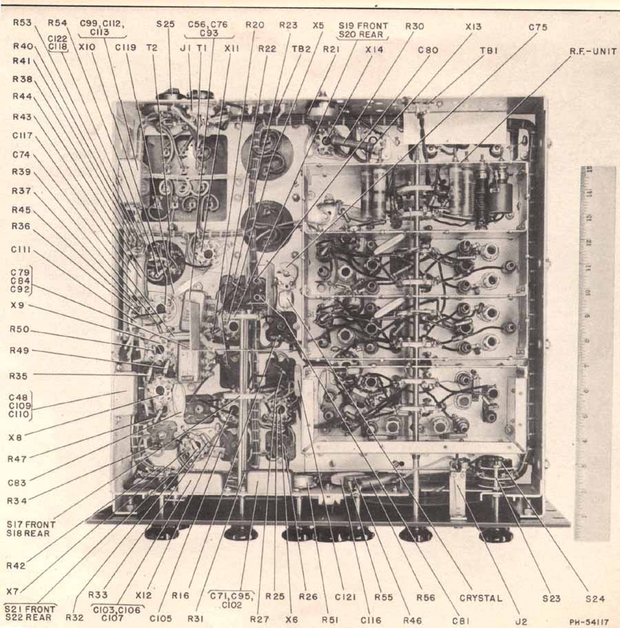
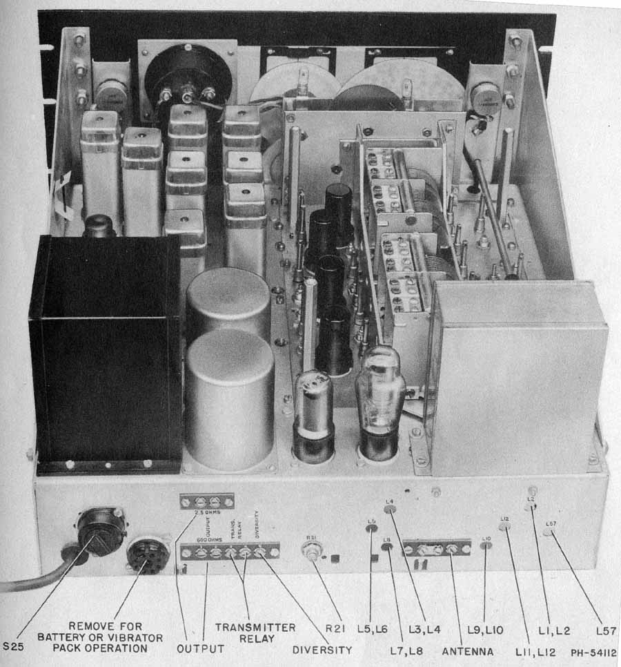
As can be seen from the above top and bottom views, the layout was extremely neat and professional The wave change switch had eight thick ceramic wafers, all with heavily silver plated contacts. On top, the RF section had a steel screen closely covering the ganged capacitor, then over the whole section was another removable screen. This radio must have been designed with EMP in mind. The right hand picture shows the top view with both screens removed.
CIRCUITRY
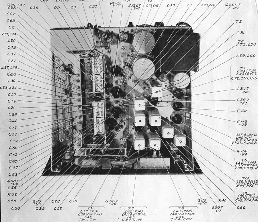
The circuitry was advanced for the time. A single conversion superhet, with two RF stages, a pentagrid mixer and three IF stages, giving more than adequate gain. There were no less than 12 tuned circuits in the IF stages, which produced an excellent bandpass shape for AM without the use of a crystal filter. Two AM positions were available, the broadest was stated to be for "High Fidelity" For CW a crystal filter was employed, although there was no phasing control. Three different bandwidths were available for CW - 3.0KHz, 1.5 KHz and 400Hz, this being achieved by varying the tapping on an IF tuned circuit.
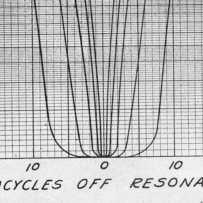 Some serious selectivity curves
 A glimpse at a part of the circuitry demonstrates
the complexity and sophistication.. Interstage RF coupling is by
ganged resonant circuits, the relatively narrow pre-mixer bandwidth reduced the
total RMS power into the mixer to great benefit. This technique is rarely
found in today's equipment designs. Note the switching circuit for the variable CW selectivity and the four tuned
circuits between the first and second IF stages.. A personal opinion -
circuits drawn in the USA, just before and after the war were not for the faint
hearted! I found them difficult to decipher.! Do you remember
when mixers were called detectors?
A glimpse at a part of the circuitry demonstrates
the complexity and sophistication.. Interstage RF coupling is by
ganged resonant circuits, the relatively narrow pre-mixer bandwidth reduced the
total RMS power into the mixer to great benefit. This technique is rarely
found in today's equipment designs. Note the switching circuit for the variable CW selectivity and the four tuned
circuits between the first and second IF stages.. A personal opinion -
circuits drawn in the USA, just before and after the war were not for the faint
hearted! I found them difficult to decipher.! Do you remember
when mixers were called detectors?
As happens today there were always "improvements and upgrades" that could be made unofficially. The 6SA7 mixer was rumoured to be more prone to overloading than the newer 6SB7Y. I knew someone who went to the USA in 1953 - a great rarity then - who kindly brought me back one of these. I could not believe my luck! I carefully replaced the original mixer, and you've guessed, there did not appear to be any improvement. I still have that tube in it's box to this day, I cannot bear to discard it.
Another suggested "improvement" was the replacement of the first RF stage 6SG7 with a 717A mushroom pentode. The latter device, I believe, was electrically similar to the 6AK5 B7G RF pentode. There may have been a slight improvement to the front end noise, but for HF and LF, the noise figure was already quite adequate.
I could go on but I won't, except to say I still have my original receiver. One day when I feel in the mood I am going hire a fork-lift to remove it from my garden shed, then I shall restore it.