THE 75S-3 RECEIVERS
All pictures are my own except where noted
You'll have to indulge me here, I just love receivers, hence lots of photos. I hope that you find the time you spend downloading them worth while!
The 75S-3 range of receivers were a development of the 75S-1/2, which basically used the receiver circuitry from the KWM-2. They incorporated a Q-multiplier, variable speed AGC decay, a variable frequency BFO and switched selectivity positions, and were thus much more attractive to use than their predecessors. Although the 75S-3 and the 75S-3B are often assumed to be similar, apart from the provision of an extra CW position on the selectivity switch, this is not the case.
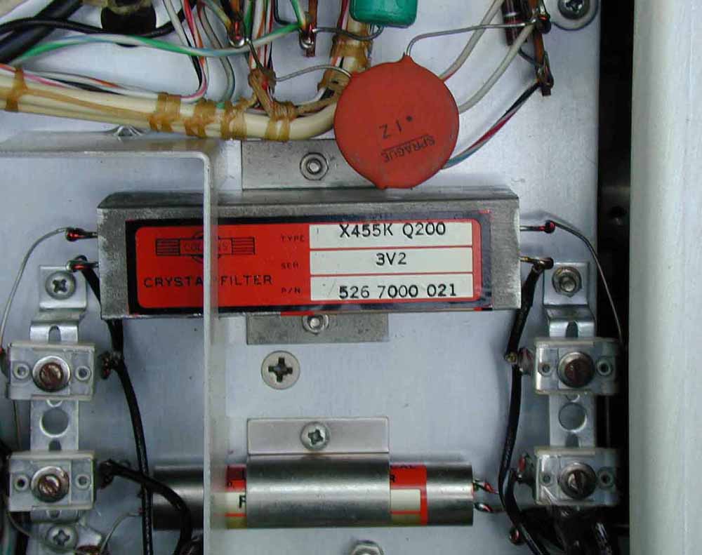
The 75S-3 had wired-in IF filters, which included the magical 200Hz 16 pole crystal filter for CW. This changed with the 75S-3B/C, the IF filters become plug-in types mounted above chassis, and the CW filter became an optional extra. The result was a considerable under-chassis layout change. There are small circuit differences also, and from the engineering point of view the 75S-3B circuitry reveals a number of improvements. However, many experienced operators still claim that the 73S-3 has the performance also edge on the 75S-3B/C.
The 75S-3C is almost identical to the -3B, except that there has been added an extra crystal board internally, doubling the number of available frequency segments and a switch on the front panel to select the new bands available.
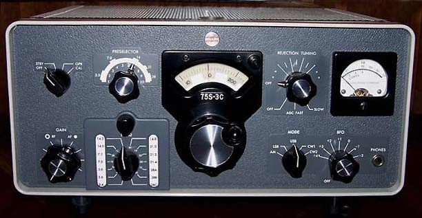
A real 75S-3C - note the wide "eyebrow" above the preselector control (not my picture)
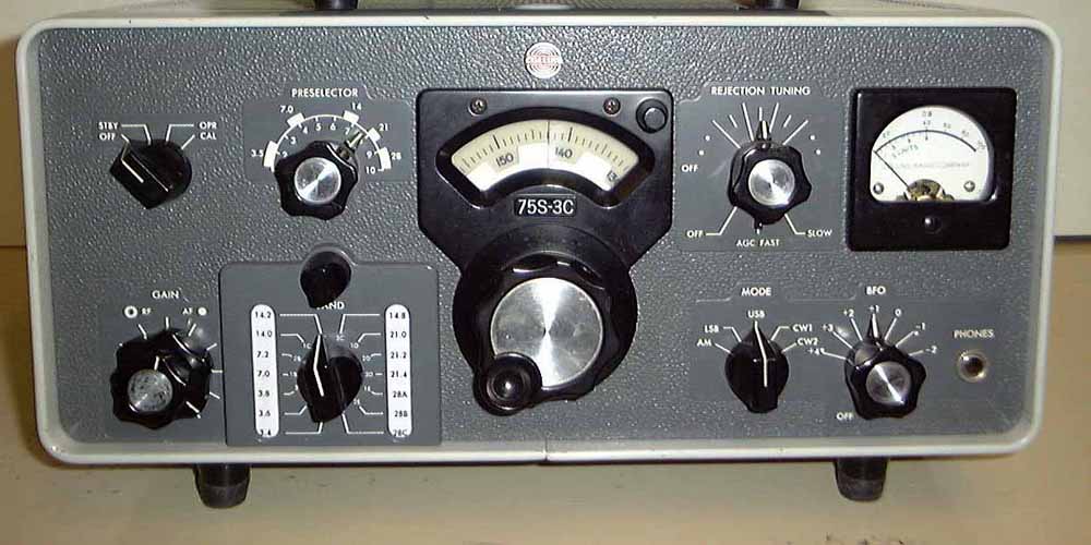
A retrofit 75S-3C . I believe that some of these were actually made at the plant using the 75S-3B panel, hence the narrow "eyebrow". However, kits were also available to convert the 75S-3B. (Not my picture)
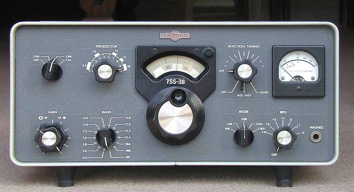
The 75S-3B
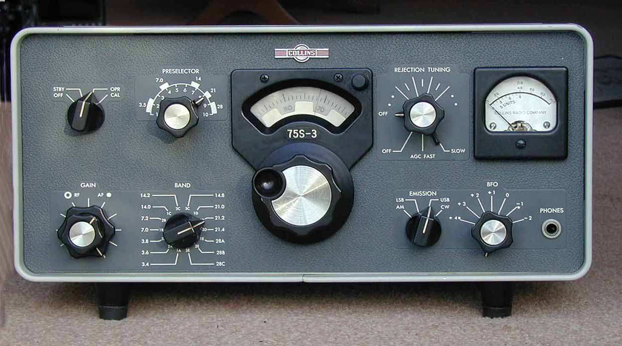
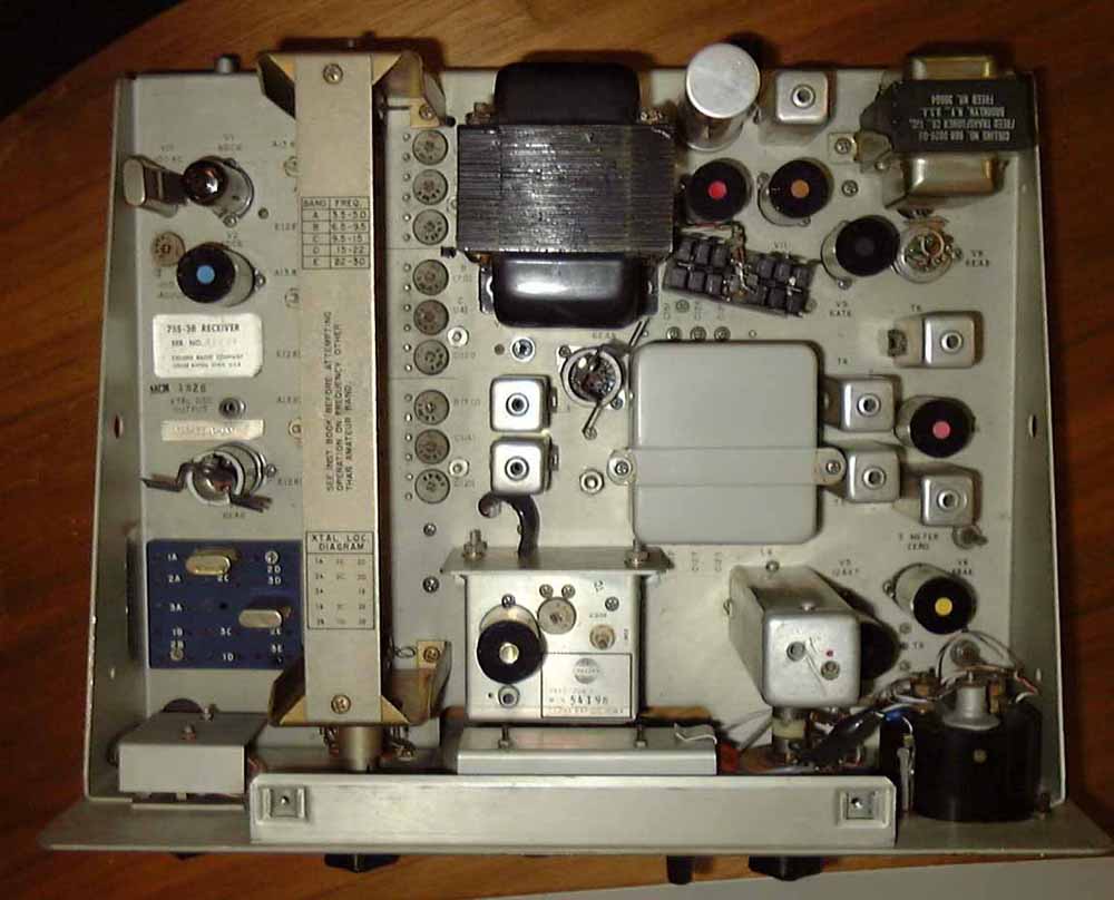
The 75S-3
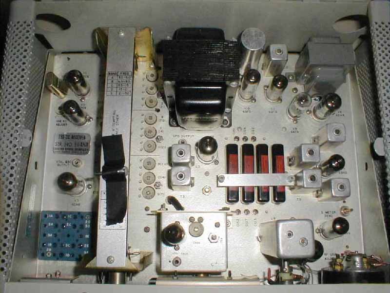
A view inside the 75S-3 and -3B will also reveal a considerable change to the layout. In a way the 75S-3B was cheapened for manufacture, by not providing the magnificent 200Hz 16 pole crystal filter as standard. The filter optionally plugs in on top of the chassis on the "B", whereas it is soldered in position below chassis on the earlier model, hence the layout differences.

75S-3 filters in position 75S-3B filters in position
The 200Hz CW filters are the large ones bearing the same identification
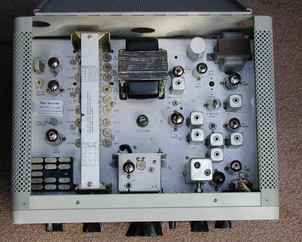
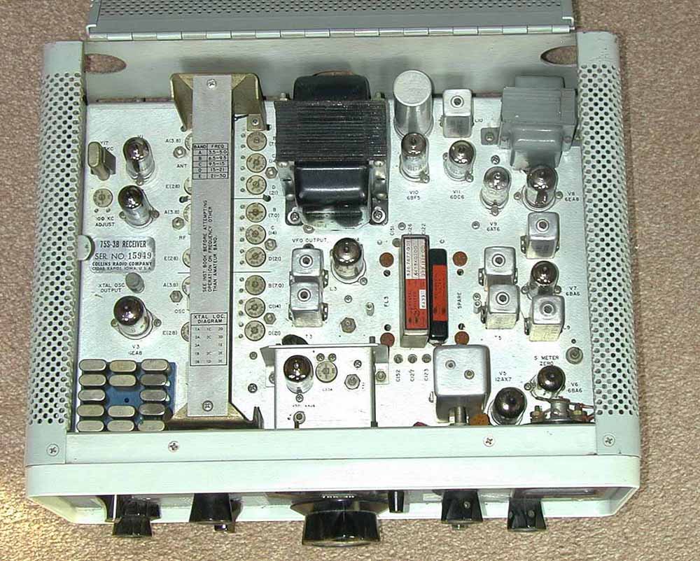
75S-3 layout 75S-3B layout
73S-3C layouts (not my picture). This is much the same as the 75S-3B. The right hand one is interesting as it shows tubesters replacing tubes - and what on earth is that "thing" to the right of the mains transformer?
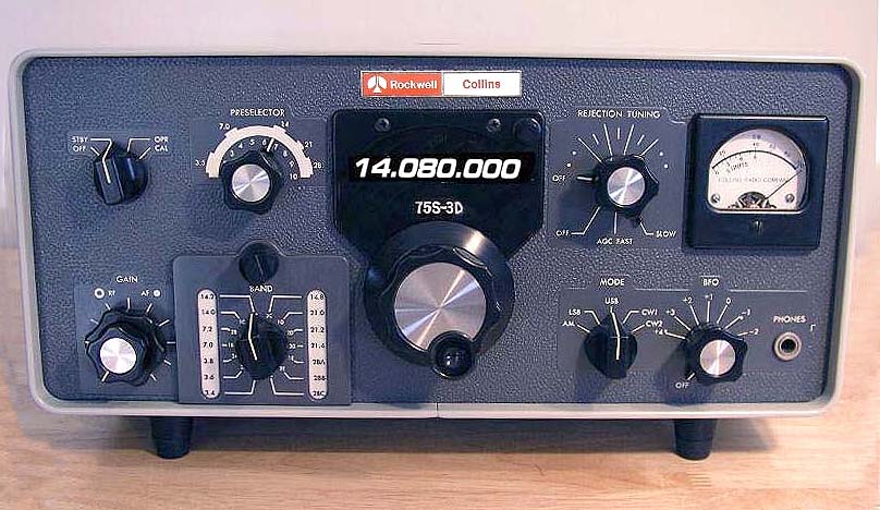
The 75S-3D
"Now what's this", I hear you say? Well forgive my sense of humor, but this is just a piece of wishful thinking on my part. Just imagine this receiver with a digital display, an all new tube lineup with say solid state balanced mixers for better IP3 and dynamic range performance. An even better performer with the same delightful appearance......... One can dream.