Home Links Contact Information
Copyright © 1995 - 2021 John Tait All rights reserved.
EI7BA Multiband Cubical Quad
" ...A thing of beauty and a joy forever..."
I wanted an antenna with the following attributes ....
1. Not too expensive
2. Covers as many bands as possible.
3. Not compromised on performance, and at least equal to a good 3 El commercial Yagi on all bands.
4. Can withstand severe weather conditions, and my salty seaside location.
5. Can be built with readily available parts.
6. Lends itself to future modification, experimentation etc
7. Fed simply with a single feed line.
8. Reasonable size.
The Quad meets all of the listed requirements with a few disadvantages, these being -
1. It is three dimensional, therefore visually more noticeable (more beautiful??) than a Yagi.
2. It limits the use of your tower for wire antennae (Dipoles etc.) because the quad arms hang below the rotator.
3. Prone to damage from ice (we get no ice in EI).
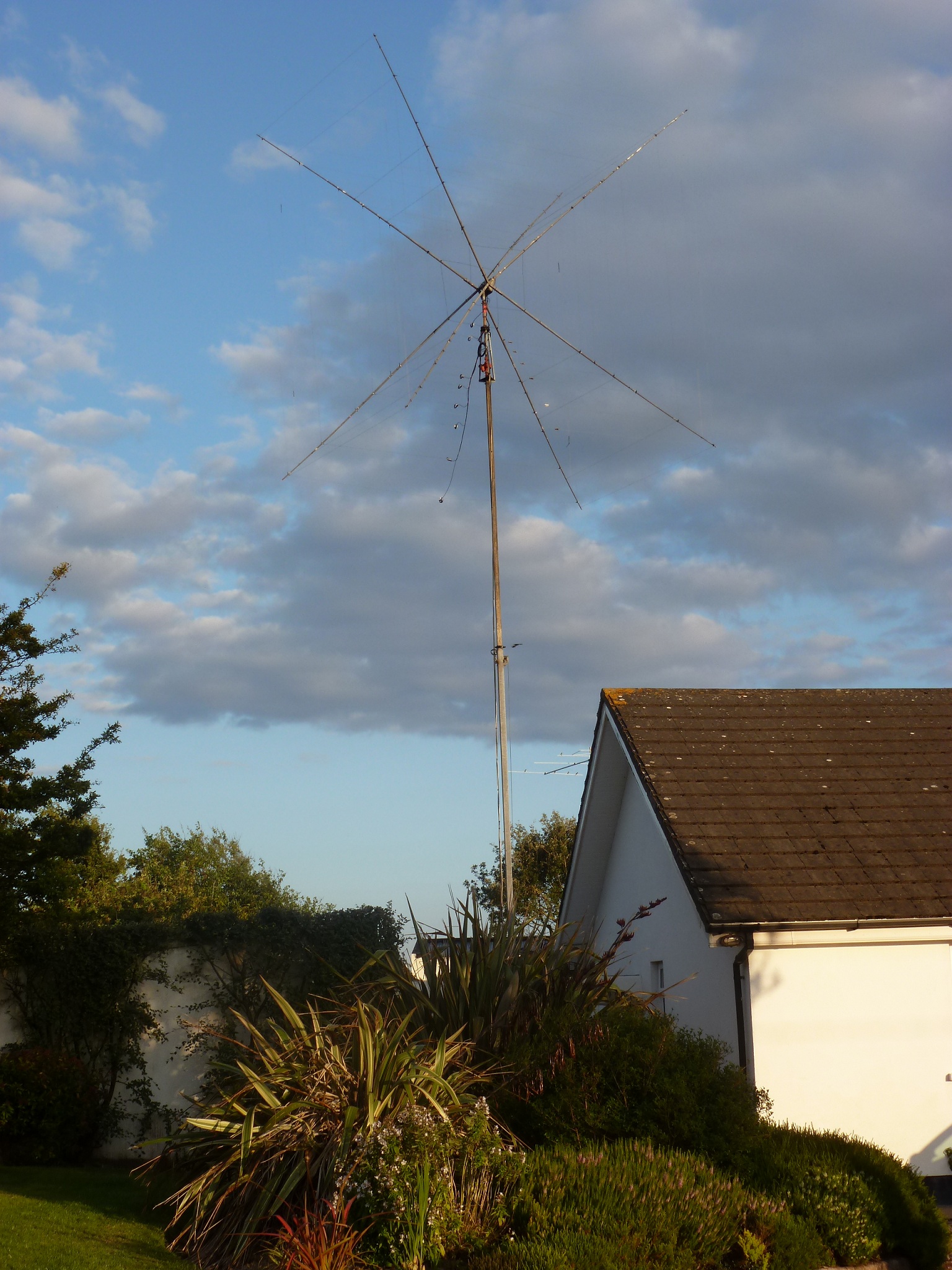
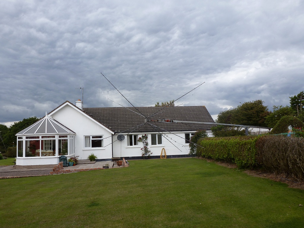
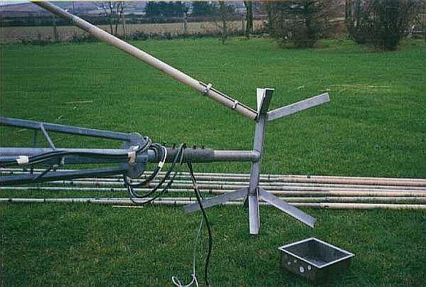
4. Very difficult to install on a fixed tower. A tilt over tower is very desirable, as the quad can be built onto the tower when tilted over.
( Pic of tower tilted over, so that the quad is easily accessible at the other side of the hedge..)
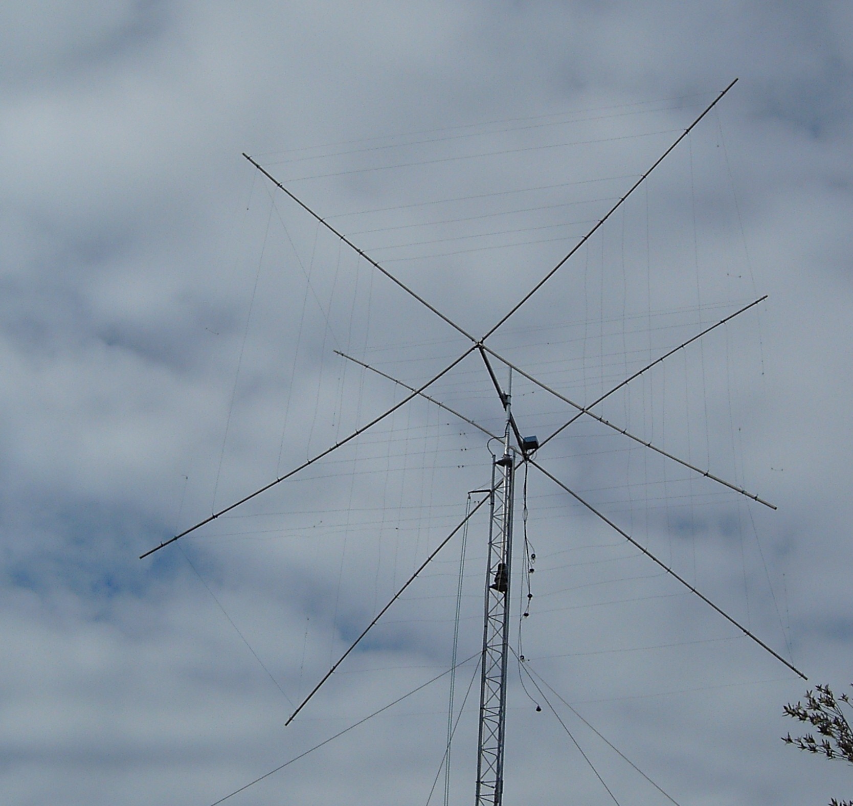
My Quad covers eight bands at present, 30m through10m on HF, and also 6m, and the European 4m band. The original plan was for a five band Quad, but as the arms were longer than required for 20m, I used the extra length to accommodate an extra band. It is up to you to decide how many bands are appropriate for you. It is a Boomless (Spider Quad, Gem Quad) design, and uses glass-fibre arms. It is fed by a single coax line to a homebrew Remote Antenna Switch. From there, separate feed lines go to each of the Driven Element feed points. There is a homebrew Choke BalUn at each feed point.
The Spider design has two advantages over the fixed length boom. Because the arms lean away from the hub at an angle of about 110deg, the element spacing is optimum for each band. Also, because of it's shape, and very short boom, it has less "bias" in a strong wind, and therefore puts less strain on the rotator.
Performance
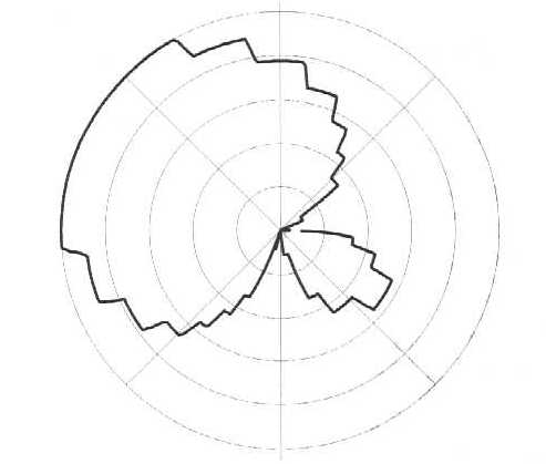
I have no accurate method to measure forward gain, but I reckon it is the text book 5-6 dBd.. F/B ratio is consistently 5-6 S points on my S meter, for all bands 20-10m. It's a bit less on 30m, but still pretty good...circa 15dB. As with all 2 element Quads, It has a wide beam width.. about 60 degrees.
(Measured plot of polar diagram..15m. Using software by I0JX and TS850 to produce the plot)
Construction -
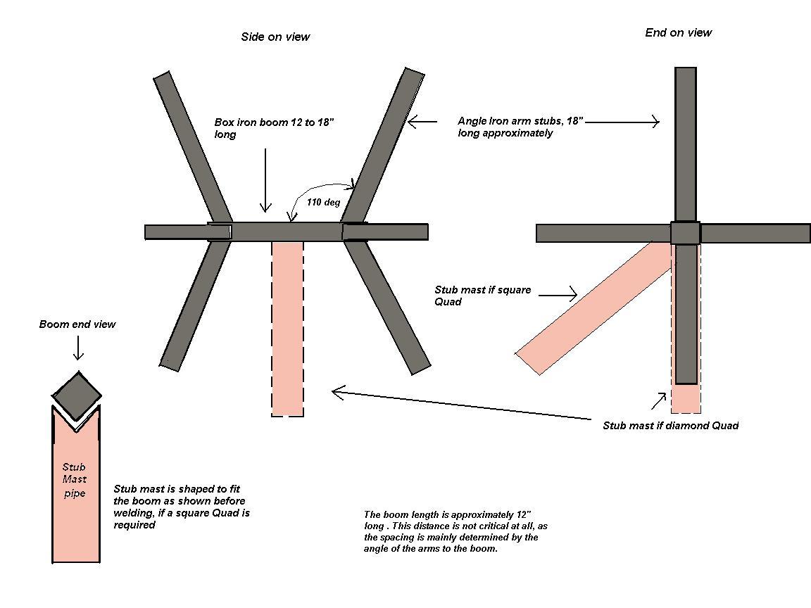
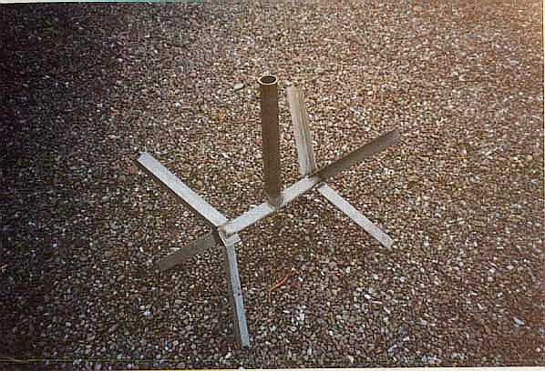
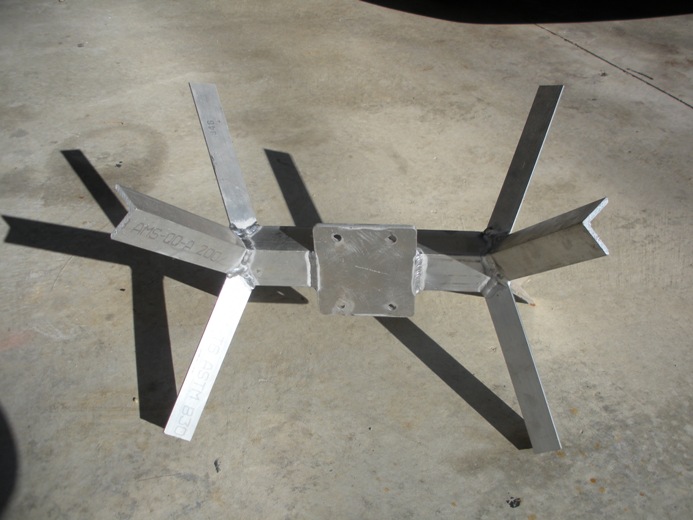
The spider was built for me by my friend Jim E18GS,(EI7M) who is an Engineer. He also built my Crank-up Tilt-over Tower. The spider is made of stainless steel. The boom is about 18 inches long (not critical), with the angle iron arms welded to the boom at an angle of 110 degrees to the horizontal. The pipe, a foot long, is welded at right angles to the boom in the centre. Depending on whether the pipe is welded to the flat side of the boom, or to the corner, gives either a diamond or a square shape quad.
( Drawing of stainless steel spider)
( Pic of spider )
(Pic of spider mounted. First arm attached)
I use the square shape. This pipe slips into the 2 inch OD stub mast coming from the rotator. My stub mast is about 5 feet long. The glass fibre Quad arms are clamped to the short angle iron arms of the spider (which are each about 18 inches long) using jubilee clips (Hose clamps).
( The W9SN commercial Quad Hub. Constructed from aluminium )
The Quad arms are often hard to source. In the USA there are a number of good suppliers, Max Gain being a popular port of call for fibreglass Quad arms of all sizes. I believe they can also be got in the UK, but here in EI, they are hard to find. I got lucky when I found a firm that made Radomes, fibre-glass casings for VHF colinears, fishing rod blanks, and other useful stuff. Unfortunately, they moved their production to China a number of years ago. My Quad arms are VHF antenna casings. They taper from about 40mm at the hub, to 25mm at the tip. They are 16 1/2 ft long, and are very strong. Even when my Quad was blown apart by winds which gusted to 115mph in 1997, the arms survived unscathed. Many years ago, I used bamboo poles, but glass fibre is so much lighter and stronger. You can also use metal arms, so long as they are not resonant anywhere near the bands intend for use. I seem to remember a USA firm which sold Quads with aluminium arms.. Gotham??
There are many different ways of securing the element wires to the arms, but whichever method you use, Do not drill the arms as this weakens them. Originally, I used two strong cable ties at each attachment point. This option is effective and cheap, but the problem with it, is that cable ties need to be replaced every couple of years. Because of the effect of sunlight, they will become brittle and weak, and will eventually fail.
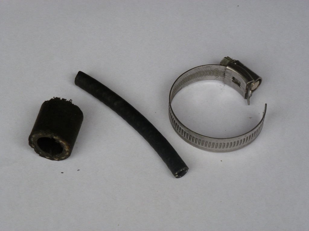
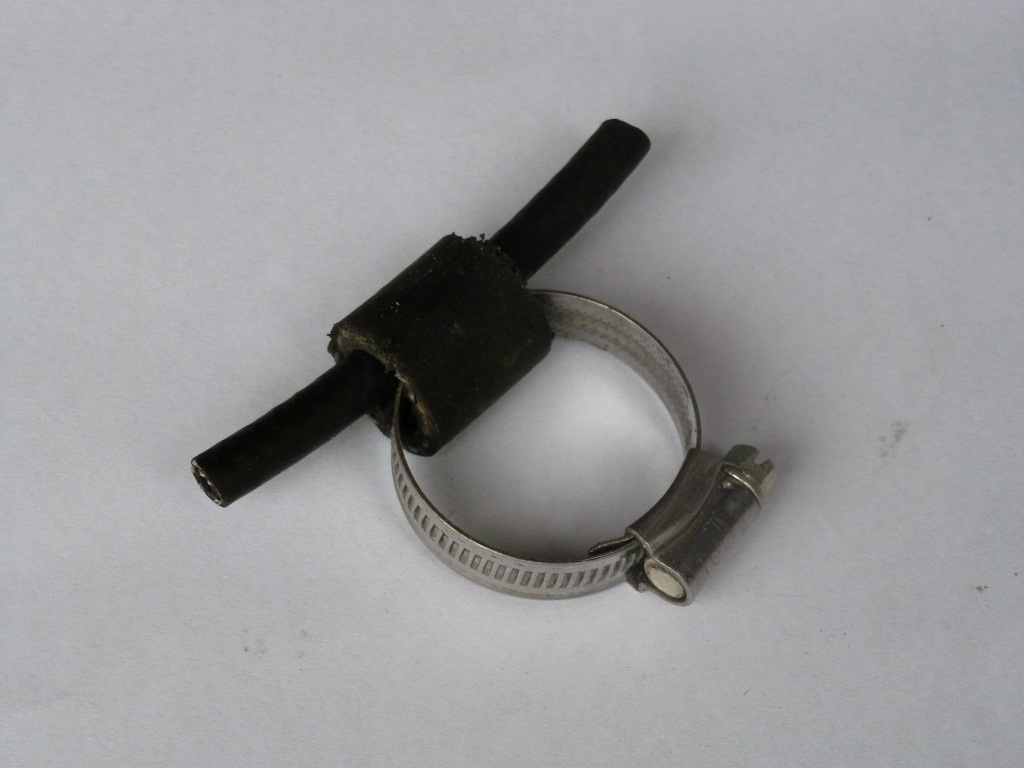
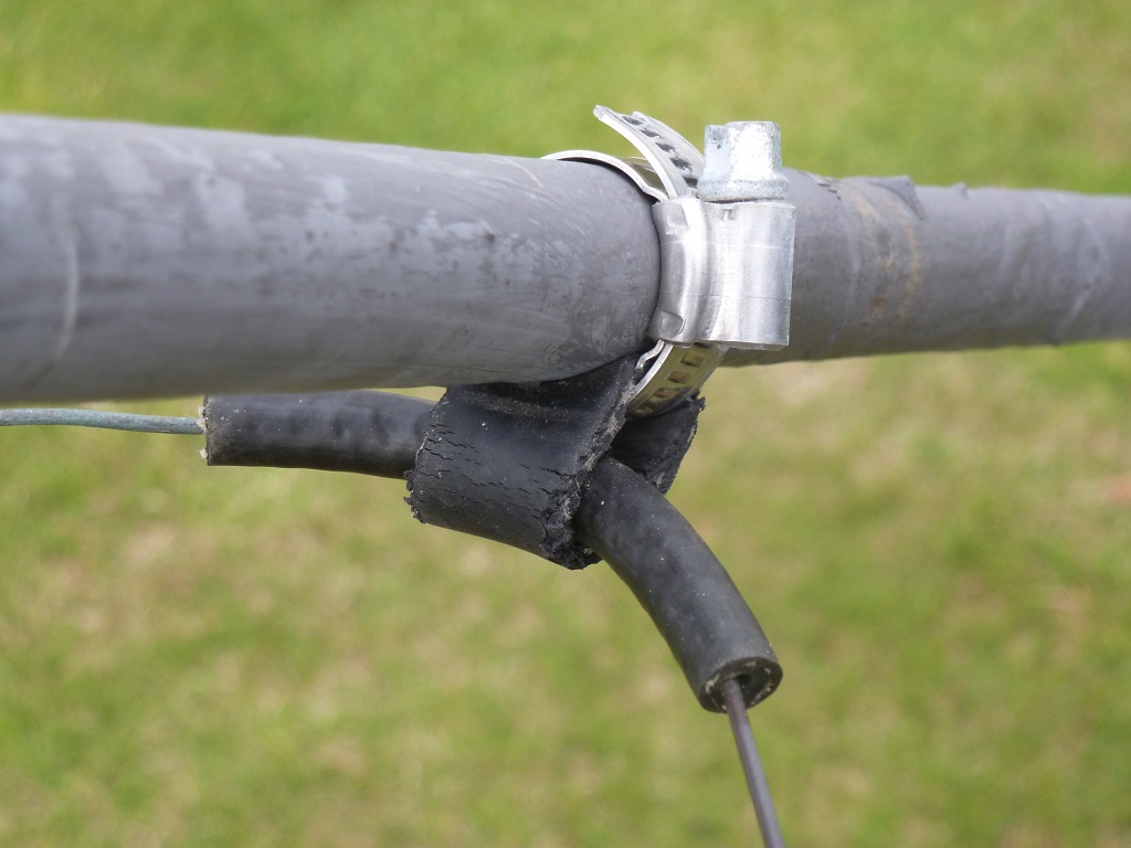
The famous "Lightning Bolt" Quads used a system which I have now copied. A short length of brake hose is used to radius the corner of the element. It in turn, is threaded through a short length (about one inch) of strong industrial hose, which is clamped to the arm by a stainless steel hose clamp. The length of brake hose acts as a shock absorber and prevents the wire from flexing and breaking at the corners, but it also allows the element wire to move through it. See pics below.
( Pics of element to spreader attachment )
Bob K2US, uses the best method that I have seen. He puts loops of nylon webbing around the element corners, the ends of which are trapped against the arm using stainless steel hose clamps. This is a very strong arrangement.
The Lightning Bolt, and K2US methods, are stronger and more durable options than cable ties, but are more expensive. However, after many years of regularly replacing cable ties, I eventually "bit the bullet", and bought the necessary stainless steel hardware.
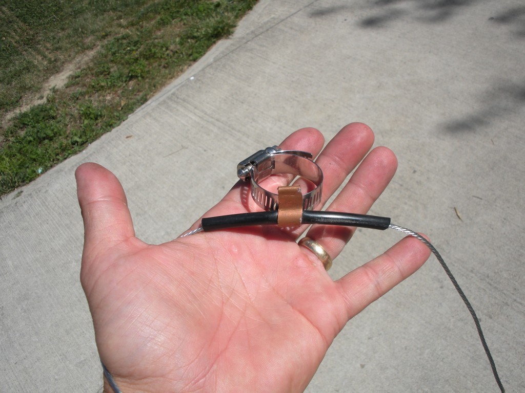
( This is Steve W9SN's version of the clamp, using a short piece of copper pipe to hold the brake hose )
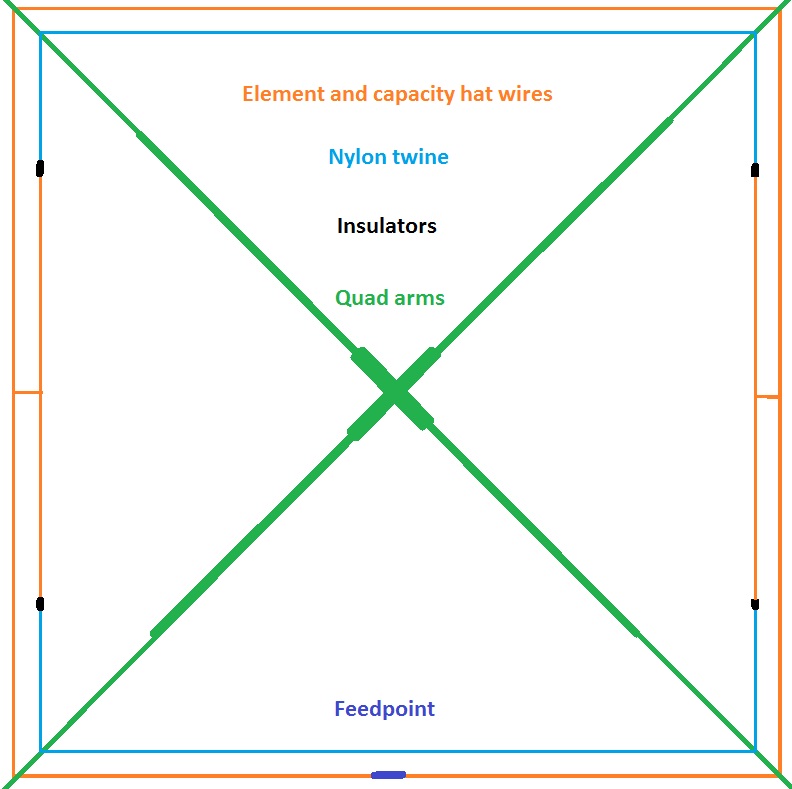
The elements should be mounted on the outside of the spreaders, because when they are tensioned, they pull away from the spreaders, and improve the insulation at the attachment points. When the elements have been attached very loosely to the spreaders, attach equal lengths of nylon twine or parachute cord, about 12ft long between the 20m driven element attachment points and the reflector 20m attachment points. Adjust the 20m element spacing with these twines. I use 11.5 ft spacing between 20m elements, which corresponds to about .18w/l spacing. Do the same at the 10m or 15m element attachment points with some more nylon twine, and then tension the elements on the arms. You now have a nice box-like construction which is very strong.
( Element to boom clamp )
Elements and loop size.
Now for the controversial bit.....
Up to quite recently, most handbooks and antenna literature informed us that we should use1005/f to calculate the size of a resonant loop. The new ARRL Handbook tells us that the correct formula is 1035/f. However, neither of these formulae are correct for a multi-band Quad. The formulae relating to a traditional three band Quad, also can not be applied to a Quad with four or more bands... Sorry folks... the books (some of 'em anyway) are just plain wrong!
There is no one correct formula for Quad loops, and here is just one reason. One parameter that will influence total length of wire in the loop, is the ratio of the wire diameter, to the enclosed area of the loop. As we will use the same wire on all bands, and each band has a different enclosed area, it follows that the formula must change for each band. This parameter however, will not impinge greatly upon our efforts here. I include it only to demonstrate the point that there is no "magic bullet".
There are two much more important variables which greatly affect the size of the Quad loops. The first of these is the wire type. Is it bare or insulated? Copper or steel? Wire diameter? For instance, If you use insulated wire, the loop size will be approximately 2% shorter than if you used bare wire. This 2% represents a 300kHz frequency shift in resonance on the 20m band. The second parameter is more subtle, but is very important in the context of a multi-band Quad.
If you were to start building your Quad one band at a time, you would soon notice the effect of this second parameter. Having completed the first band, say 20m, and adjusted it to perfection, you would be dismayed to find that as soon as you fitted the 17m elements, your 20m Quad no longer works as it should! So what's going on here? Every element in the nest of elements affects the elements near to it, and is itself affected by those same elements. They have a loading effect on each other which is a bit like adding a small capacity hat, or an inductor to each element. This loading effect on it's own, means that the element size will be less than what the traditional formula dictates.
Do not attempt to make any adjustments to your Quad until ALL elements are in place!
Ok! so where do we go from here? Well first of all I'm going to give you a "ball park" formula. Yes! I know that I just said that there's no "magic bullet", but we need to start somewhere. Working backward from the loop sizes that work for me, using 1.5mm bare hard drawn copper wire, this works out to be 990 divided by frequency for the driven element, and 1015 divided by frequency for the reflector. Don't forget that my measurements are for bare copper wire. If you use insulated wire, your elements will be about 2% smaller.
OK.. Here are my element dimensions and other information... We will discuss the 30m Linear loaded elements later on.

| BAND | Driven El | Ref El | Resonant Freq | El Spacing | SWR | F/B "S" Points | |||||
| 30m | 84' | Loading wires | 12' | 85' | Loading wires | 13' | 10.05 mHz | 13' 6" | 1.2 | 4 | |
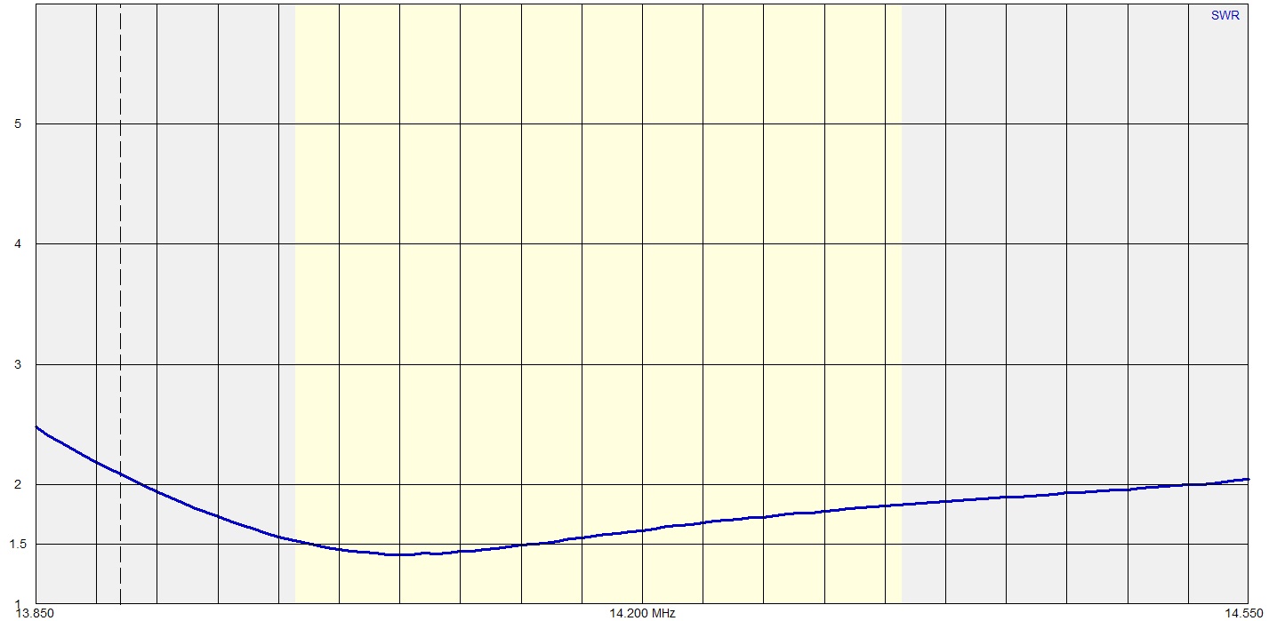
| 20m | 69' 10" | 72' | 14.12 mHz | 11' 3" | 1.4 | 5 | |||||
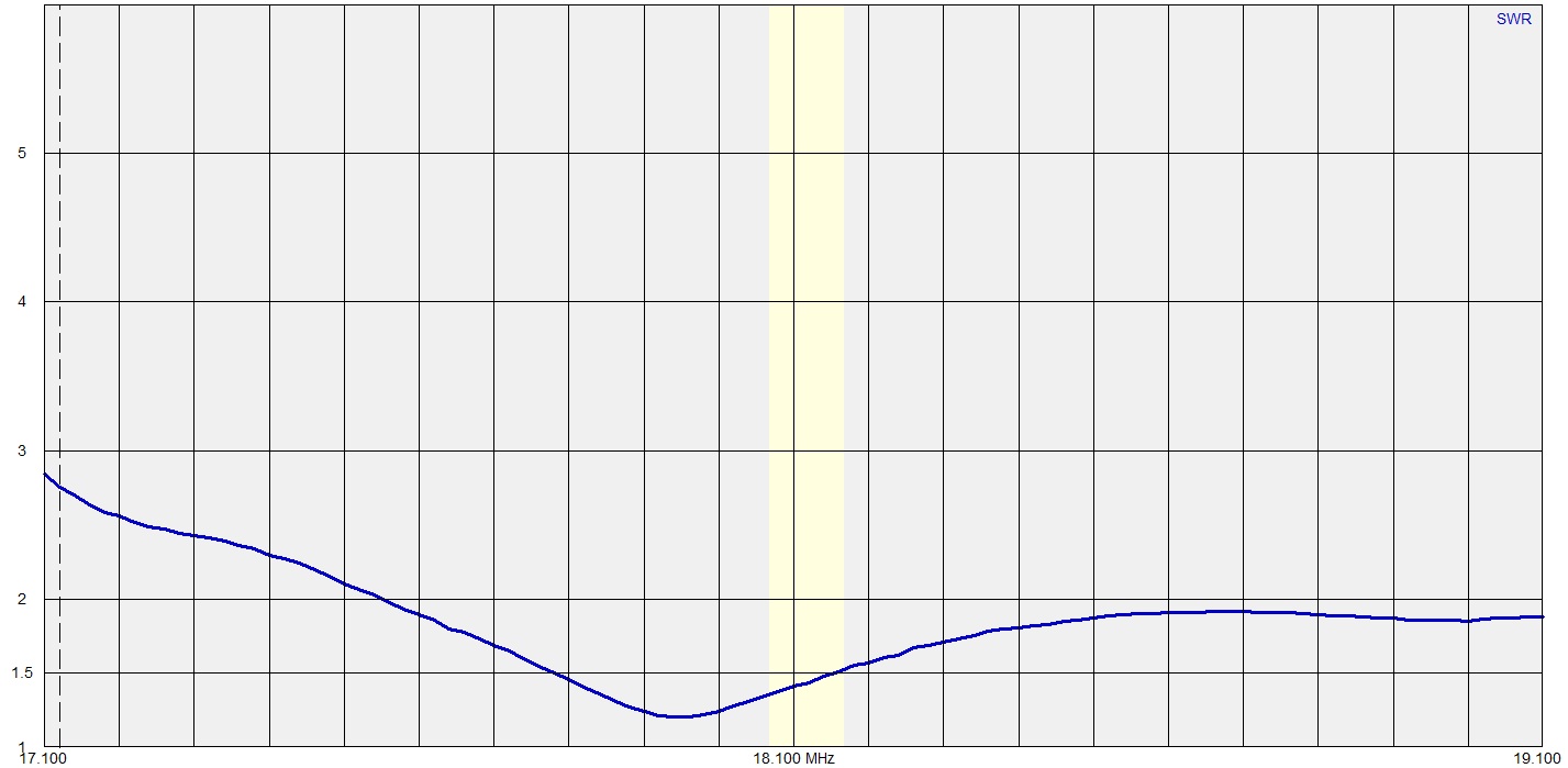
| 17m | 54' 3" | 56' 2" | 18.05 mHz | 9' 2" | 1 | 7 | |||||
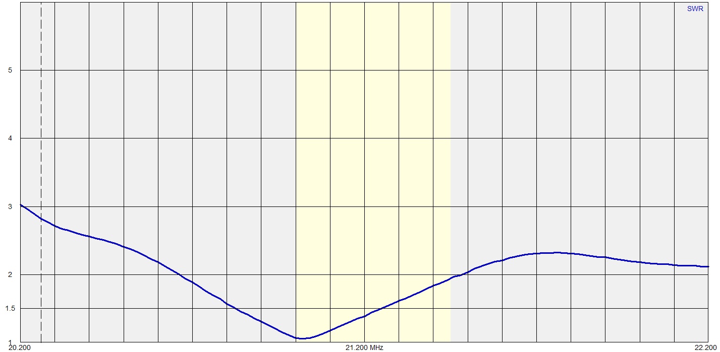
| 15m | 46' 7" | 48' 3" | 21.04 mHz | 7' 8" | 1 | 6 | |||||
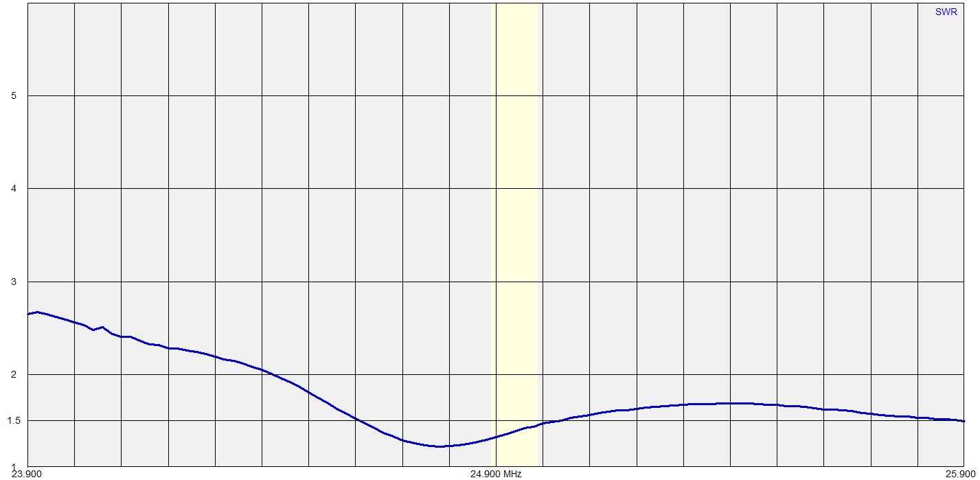
| 12m | 39' 3" | 40' 11" | 24.96 mHz | 7' | 1 | 5 | |||||
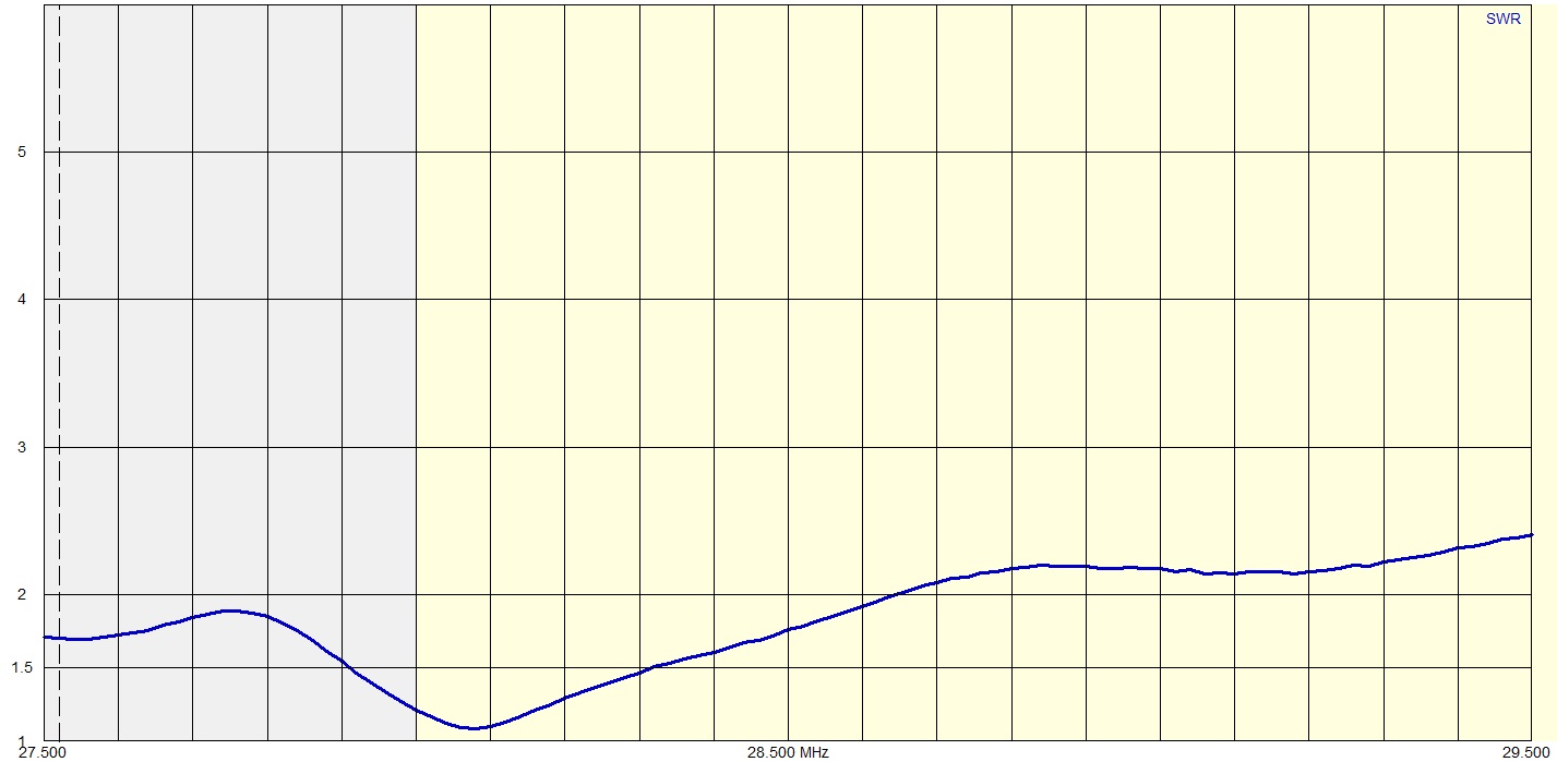
| 10m | 34' 11" | 35' 9" | 28.35 mHz | 6' | 1.2 | 4 |
A number of these quads have been built, using these dimensions, with slight variations in wire diameter, but mostly using bare hard drawn copper wire. All have delivered the goods with very little adjustment of element sizes. They all give good gain, f/b, and bandwidth.
Feeding, resonance, and matching.
When feeding a 5 band quad, it is not advisable to parallel feed all the elements. I found that if I joined all the feed points together to a single feed line, results were mediocre, with reasonable performance on 20m and17m poor on15m, but very poor on 12m and 10m. There is a lot of interaction between elements, giving a bad pattern, poor f/b ratio and very little gain on 10 and 12m..
There are two major detrimental interactions. 10m is an harmonic of 20m, so the 20m loop will accept power when transmitting on 10m. The 10 and 12m bands are so close in frequency, that they tend to see each other's elements as parasitics within their own band.
If you absolutely refuse to use separate feeds, then you should at least use two feed lines, grouping 20, 15 and 12m on one line, and 17 and 10m on the other.. This should go some way to improving matters.
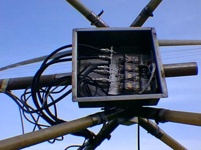
( Pic and schematic of the Relay box with the 17m loop selected.
Note that all unused loops are DC grounded at the relay box )
I use a single feed of 50 Ohm hardline to the tower base from my shack, and RG 213 coax from the tower base, to the centre of the Quad spider. There I have mounted a stainless steel box. In this box I have a homebrew Remote Antenna Switch. This consists of nine medium sized 24v relays, with good quality contacts. These act as single pole, double throw switches. I run a multi-core cable from the switch box in the shack to the relay box. This multi-core cable allows me to switch bands by putting 24v on the appropriate relay. The unused relays are wired so as to ground the feed points of the unused driven elements.
The switching at the shack end, is controlled by an Automatic Band Decoder, so band switching follows the rig automatically.
( Pic showing the stainless box mounted on the spider, with the homebrew switchbox inside. The stainless steel box has a weatherproof lid, which was removed for the pic)
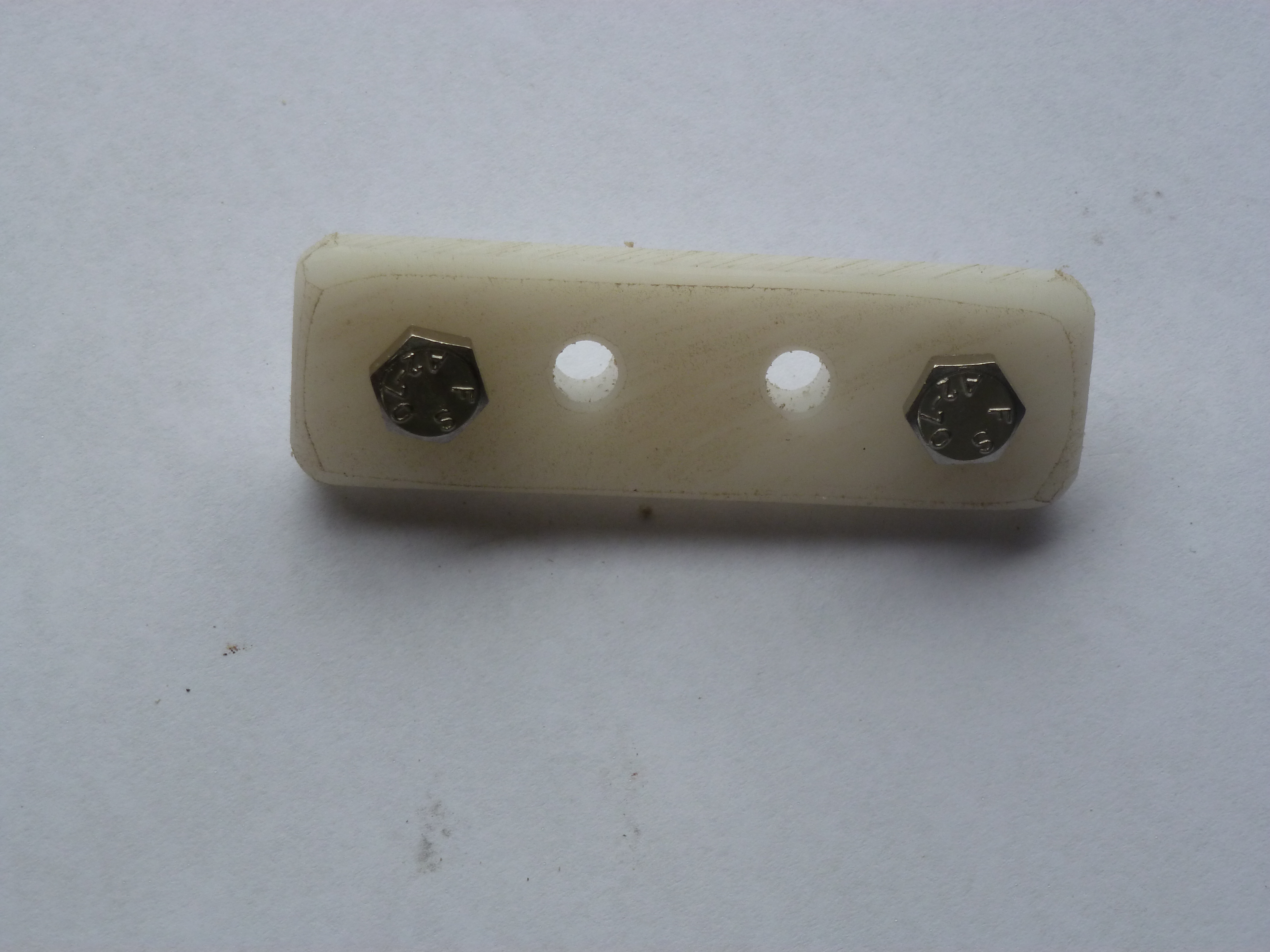
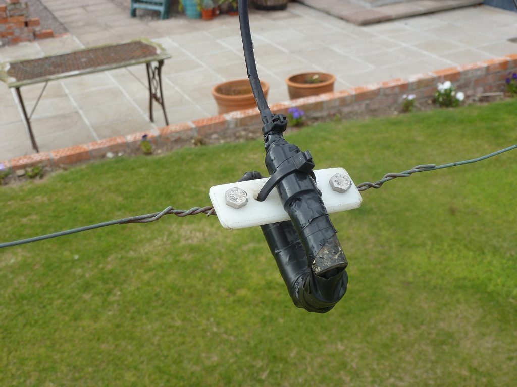
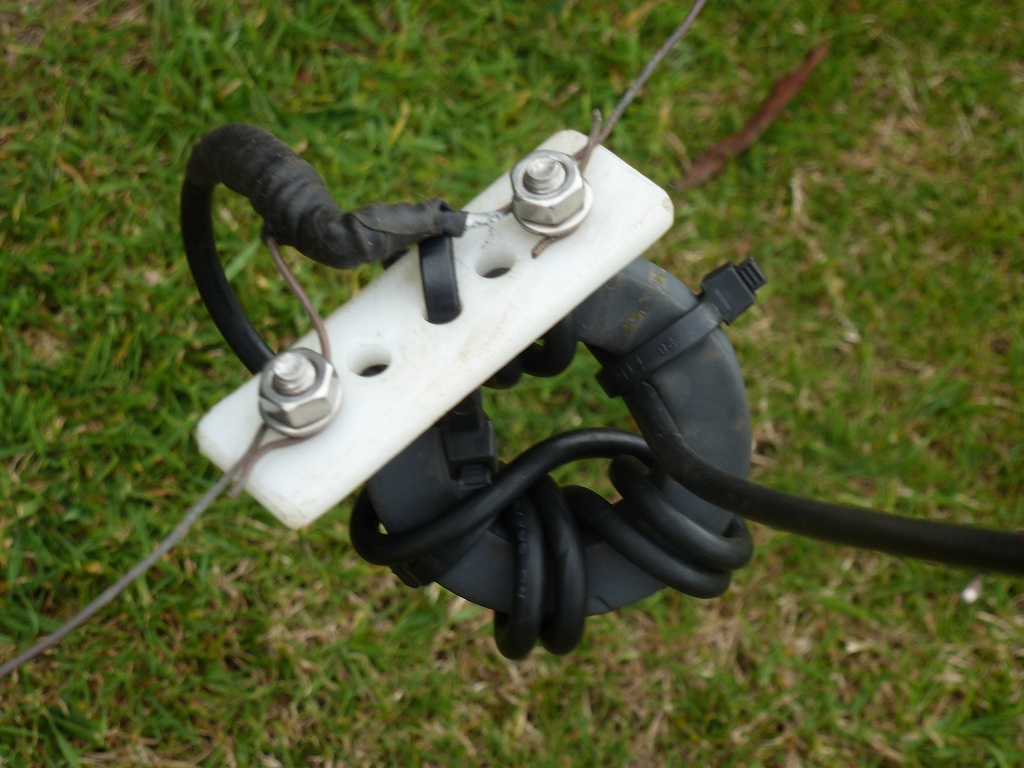
The RG 58 coax feed lines from the driven elements, use PL259 plugs to connect to the Remote Switch Box. They are made off in a pig-tail at the other end, where they connect to the Quad loops, using homebrew Nylon insulators, and stainless steel bolts.
(Homebrew Nylon feed point insulator, with stainless steel connection bolts)
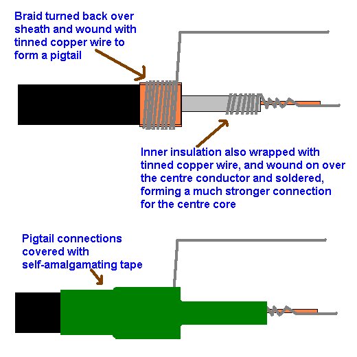
A Pig-Tail connection won't last very long, unless it's made properly. You need to use something like 18 SWG soft copper or tinned copper wire, connected as in the drawing below
As we discovered earlier, the elements in a multi-band Quad will be smaller than in a mono-bander, because of the loading effect that multiple elements have on each other. The proximity of the elements to each other in a multi-band Quad, also has an effect on the feed impedance of our driven elements.
A mono-band Quad will have a feed impedance of about 100 Ohms at resonance, giving us a 2:1 SWR in a 50 Ohm system. The usual solution to this problem is to use an electrical quarter wave length of 75 Ohm coax, connected between the feed point, and the 50 Ohm coax feed to the shack. This 75 Ohm coaxial matching transformer creates a very nice match to 50 Ohm coax.
In our multi-band Quad however, the feed impedance is lower, due to the proximity of the other elements. The impedance of our multi-band Quad varies from about 80 Ohms to 30 Ohms at their resonant points (X=0), with most bands coming in very close to 50 Ohms. This happy consequence, means that we can feed our elements directly with 50 Ohm coax.
( Choke BalUn using #43 ferrite beads )
( Choke BalUn using F-240-43 ferrite toroid )
A Quad is a balanced antenna, and should be fed in a balanced manner. To this end, I use a choke BalUn at each feedpoint. At the 30, 20 and 17m feedpoints, I use 12 turns of RG58 wound as shown in the drawing below. Basically, you just wind the last eighteen inches or so of the coax feed through the core as shown. For 15, 12 and 10m I use about 8 turns on an F-240-43 toroid, or 12 turns on an F-240-61 toroid, or 6 to 8 #43 ferrite beads slipped over the coax, as in the picture above. I use cable ties to keep the feed lines together, and to tie the chokes to the feedpoint insulators. This arrangement is fairly light and strong, and survives well.
Steve G3TXQ, has a marvellous "Ready Reckoner" for Choke BalUns. You'll find it hidden away amongst all his other wonderful stuff, which includes the definitive treatise on the Hexagonal Beam.
Up to Christmas 1997, I fed the loops using 75 ohm 1/4 w/l matching transformers which were connected back to the switch box. This was to match the theoretical 100 ohm to 120ohm feed impedance of the driven loops, at the wider spacing that I use. (.18 w/l, as against the more traditional .12 w/l). However, having had damage to the quad on Christmas Eve 1997 during 110mph gales, I decided to feed the loops directly from the switch box with 50 Ohm coax, as I was in a hurry to get back on the air. I was amazed to find a nice SWR curve on all bands (1:1 in most cases at resonance). This situation puzzled me, but as everything was working very well, I didn't worry too much about it, and gladly went along with the old addage "If it ain't broke...don't fix it..."
Around this time, I had some interesting email conversations with L B Cebik W4RNL. I had been experimenting with feeding the Quad at different positions. This interested LB, so he modelled my Quad, and investigated the difference between corner fed, and traditionally fed Quads. You can see the results at his 2element multiband Quad section . He came up with an explanation as to why my SWR curves are so good without the 75 Ohm 1/4 w/l transformers. It seems that when you have umpteen elements all nested together, the feed impedance is changed from the single loop value of 100 to 120 ohm value, to anything from 30 to 80 Ohm, depending on whether the loop is in the middle of the group, or on the outside.
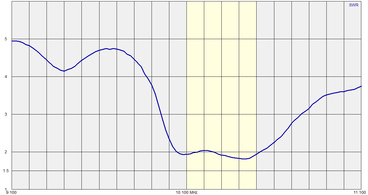
( SWR Curves, measured with a Rigexpert AA-250 Analyser )
Extra Bands
As I stated earlier, my quad arms are 16.5 ft long. This meant that they were longer than needed for 20m by about 1.5 ft. As it is very easy to chop off the surplus length, and not so easy to add it back on, I decided not to " look a gift horse in the mouth", and to use the extra length to my advantage. Originally, I used the extra arm length to accommodate a bent dipole for 40m on the Reflector arms, and a capacity hat loaded loop for 30m on the driven side. This arrangement worked very well indeed.
( 40m folded, bent dipole )
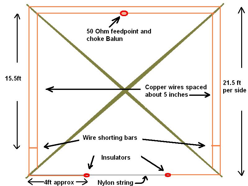
On 30m, it is a full wave loop, attached to the arm tips on the driven side of the quad. The two linear loading wires (as per G3FPQ) are spaced about 6 inches in from the loop sides, and are connected to the loop at their mid points. These wires are adjusted for resonance.
I also added elements for 6m and 4m, which gave me a total of nine bands. All bands except 30 and 40m gave good gain and F/B ratio. Not bad for a single mechanical structure.
Two elements on 30m
A couple of years ago, I had an interesting email from Rob ZL3RG. His mail was also an important catalyst. Around the same time as Rob's email, I had built a phased array for 40m, so my bent dipole on the Quad was becoming redundant. I had been toying with the idea of replacing the 40m dipole with a loaded reflector element for 30m. I knew it would work, as for many years, I had lusted after a large multi-band Quad design by David Courtier-Dutton G3FPQ, in the ARRL Handbook. This design used capacity hat loaded elements for 40m. I felt safe in recommending this approach to Rob, as I already had a single element working well on my own Quad. (see above). He decided to go ahead and build it. Rob has a Lightning Bolt Quad, so he had to extend the arms by a few feet, to accommodate the 30m elements.
A short time after his initial email to me, Rob happily confirmed that he had built the 30m add-on, and was having great success. He sees 4 to five S points F/B, and good nulls off the side. He seems to have a pileup to Europe every time he shows on 30m CW or digi-modes. In fact, I rarely see any ZL station other than ZL3RG spotted on 30m.
( ZL3RG's Lightning Bolt Quad, with 30m loaded elements )
Rob's success was the catalyst I needed to get off my backside and put the second 30m element on my own Quad.
It didn't take too long to remove the 40m dipole and rig the 30m reflector element in it's place. After some tweaking, I ended up with a total of 84ft of wire in driven loop, and 85ft in the reflector. The driven elements capacity hats are 12ft in length, and the reflector hats are 13ft each. The hats are spaced six inches from the sides of each loop, and are connected at their centre points to the centres of each vertical side of the loops.
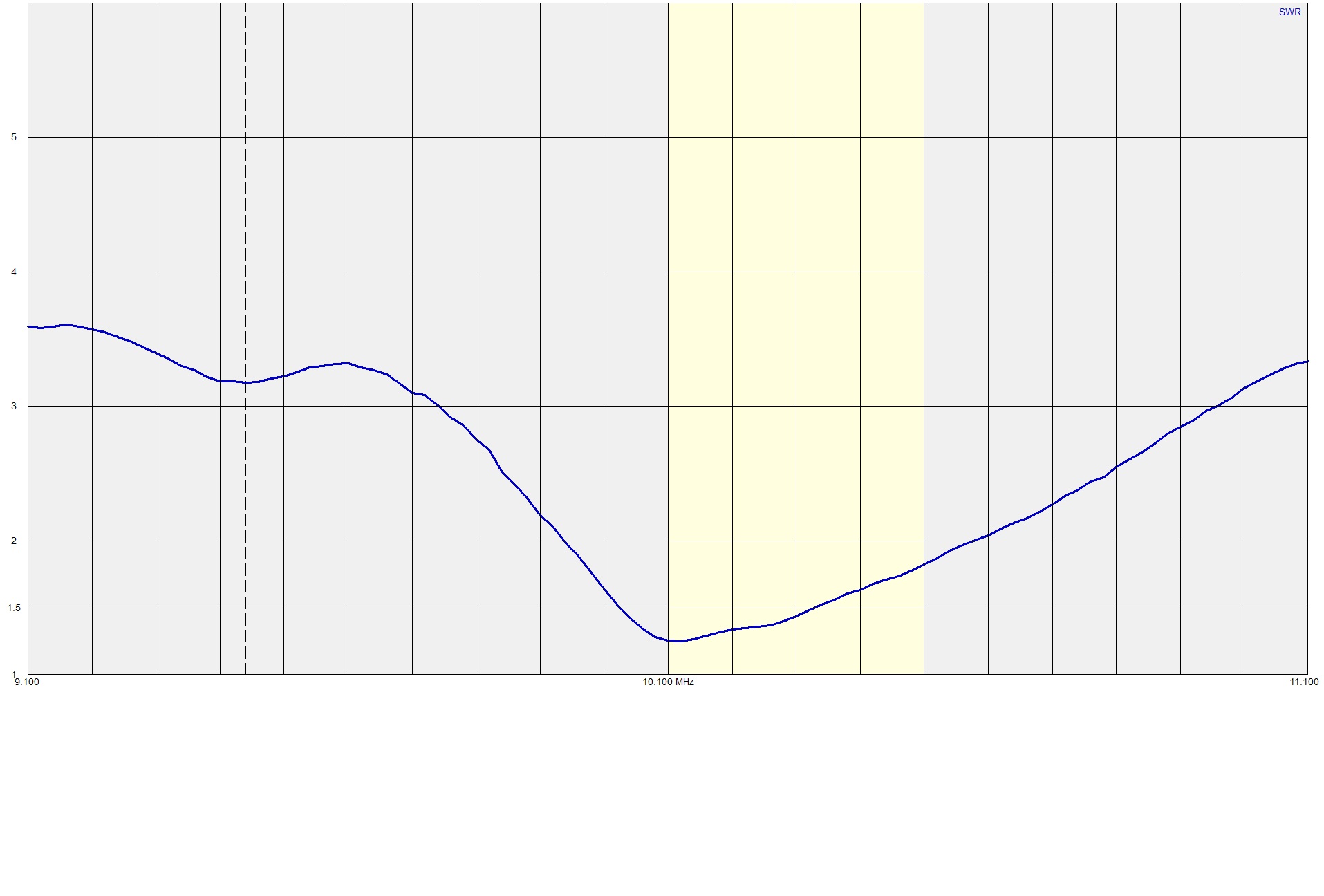
When I checked the 30m SWR, it was rather high at resonance. Around 2:1. The feed impedance was about 90 Ohms. Even though it was working very well, I decided to use a 1/4 wavelength 75 Ohm transformer, to lower the SWR.
This brought the SWR to a very satisfactory 1:3 to 1. See the SWR comparisons below.
( 30M SWR plot fed straight with 50 Ohm coax )
( 30M SWR plot with 75 Ohm 1/4 wavelength transformer )
Home Links Contact Information
Copyright © 1995 - 2021 John Tait All rights reserved.
All pages and content there-in, are the intellectual property of the author, and protected by law.
All pages and content, are subject to change at any time, without notice.