NOTE: Since putting this page on the internet I have received a number of requests for a copy of the assembly instructions. Click here to view a printable copy of the assembly instructions.
One of the best antenna values on the market is the LightningBolt Quad. At about half the cost of a tri-band yagi, you get five band coverage with a single coax feedline and excellent performance from a light, low wind load antenna. Like anything else in life, the quad has its pros and cons, but I believe the pros outweigh the cons. I have been using the LightningBolt Quad since 2001 and want to share my experiences with assembling and installing the antenna.
The antenna is shipped in two boxes. An eight foot long box contains the boom, fiberglass spreaders, and boom to mast plate and clamps. The second smaller box contains all the hardware which includes hose clamps, wire holders, plexiglass insulators, two spools of wire, a balun, the spreader hubs, and all the nuts, washers, lock nuts, and bolts needed to assemble the antenna. All of the antenna hardware is stainless steel except for the galvanized boom to mast clamps. A detailed set of instructions is also included in this box. To ensure that the finished product performs as advertised, it is important that you follow the assembly instructions carefully and precisely. If you are not mechanically inclined, this project will prove to be a difficult one.
The quad's components...
 |
 |
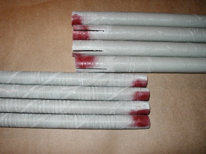
| The quad spreaders consist of two fiberglass tubes which telescope together (for UPS shipping). The red paint marks indicate which ends to fit together. The end of the spreader that attaches to the hub is approximately 1.25 inches O.D. The spreaders taper down to about 1.0 inch O.D. | For high durability and strength, the spreaders are made of filament wound fiberglass. They are reinforced at the joints for additional strength and are resistant to the sun's UV. |
 |
 |
|
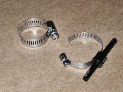
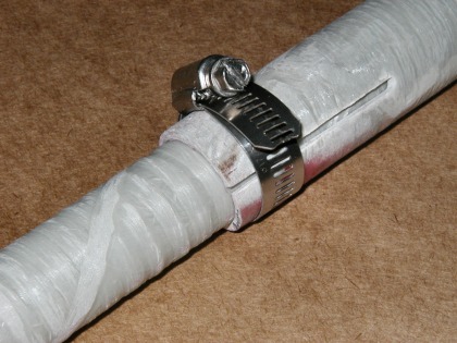
| Two varieties of hose clamps are used on the antenna. Stainless steel hose clamps hold the spreaders to the hub and wire holders with stainless steel hose clamps hold the wire loops in place. The wire holders are a special design, made from high strength UV resistant air brake tubing attached to a stainless steel hose clamp. The strength and flexibility of the tubing acts as a shock absorber. |
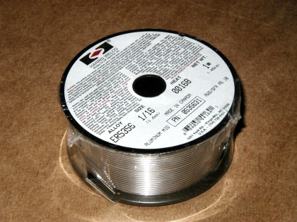
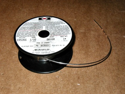
The
reflector and driven elements are 1/16 inch diameter aluminum alloy 5356. The wire is high strength
(80,000 psi), will not stretch or corrode and is very light
weight. The wire is very stiff (brittle) and
springy and can be bent in a tight radius only once. One spool
has 270 feet of wire, enough to make one element for each of the 5 bands. |
 |
 |
|
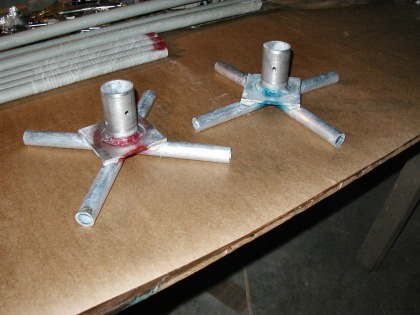
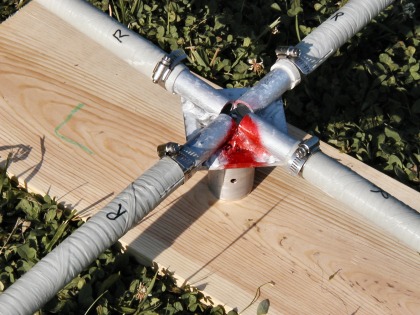
| Two
hubs with spiders hold the spreaders for the reflector and driven element. The spreaders attach to the spiders with hose clamps. The spiders are thick walled 6061-T6 aluminum welded and machined for a tight fit to the boom. The hubs/spiders attach to the boom with two bolts. |
When
measuring for the placement of the wire holders, the measurement
includes the length of the aluminum tube on the hub. Your tape
measure should be inserted on the end of the tube welded to the plate. |
 |
 |
|
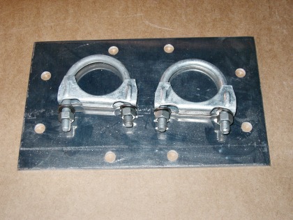
| The
boom to mast plate and U-bolts. The boom to mast plate is
1/8 inch aluminum. The U-bolts are hot dipped galvanized and will
not rust. |
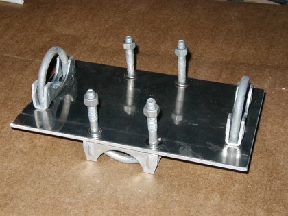
The
assembled boom to mast plate. When tightning the clamps on the
boom be careful not to over tighten. They don't have to be super
tight to hold the antenna in place. Over tightening will collapse
the boom and weaken it casing it to bend in the wind. |
 |
 |
|
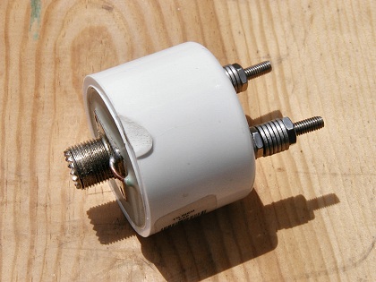
| The
2:1 balun is rated for 1500 watts and has handled my 1500
watt amplifier with no problems. Stainless steel hardware
is used to attach the element wires to the transformer. I seal the
end with the coax connector with RTV once the feedline is attached. |
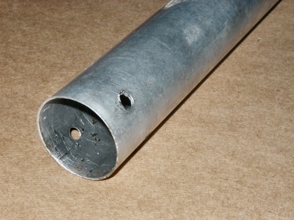
The 8 foot boom is 2 inch O.D. thin wall alluminum alloy. It is very light like the rest of the antenna. The ends are color coded to accept the matching spreader hub which is similarly color coded. |
Assembly of the antenna is rather labor intensive, requiring a lot of measuring, so keep a tape measure and a felt tip marker handy during assembly. Assembly begins with reading the instructions to familiarize yourself with the assembly procedure and the "do's and don'ts" included in the instructions.
The first step is the assembly of the fiberglass spreaders. You will have 16 lengths of fiberglass tubing. Eight will be a larger diameter than the remaining eight. These pieces telescope together to make eight spreaders, four spreaders per element. The two fiberglass tubes are held in place with a hose clamp as shown below. Once you have the length correct, tighten the hose clamp to secure it and make sure it is tight. When it is tight you cannot rotate the two tubes inside of each other. This is the only piece of the antenna hardware that needs to be tight at this point. During the rest of the assembly process do not tighten the parts because some adjustment will be necessary when installing the wire loops. Each of the eight assembled spreaders will be approximately 12 feet 9 inches long.
 |
||
| The spreader telescoping fiberglass tubes are held together with stainless steel hose clamps. The spreader tubes have a clear coat on them that resists UV. |
|
A side note ...
The reflector and driven element spreaders are the same length, although the driven element spreader could theoretically be shortened about 6 inches. I asked Mike at LightningBolt about this. He does not recommend doing this because if one element has shorter spreaders, under high wind conditions, it could cause a "wind-mill" affect causing unbalanced forces to act on the antenna which will try to rotate it in the wind. Mike indicated that this is an issue with yagi antennas and a bigger issue with the survival of log periodic antennas in high winds. So to insure there are balanced forces under wind load, the spreaders are kept the same length.
End of side note ...
The reflector spreaders are assembled first, then the driven element. It is a good idea to mark the two sets of spreaders so you can tell them apart. The only difference between them is the placement of the wire holders.
Once each of the eight spreaders are assembled, measured, fastened with a hose clamp, and tightened, the next step is to install the wireholders. There is a total of 40 wire holders on the 5 band quad (24 on the 3 band model), so this step can take some time to complete. Starting with the reflector, install a spreader on the hub. Each hub is color coded with either a red or blue paint mark. Make a note of which one you use for the reflector and driven element spreaders so the correct one will be used during final assembly. The hub holds the 4 spreaders and fits into the end of the boom. Please note that all measurements for the placement of the wire holders are made from inside the hub. This effectively adds about 4 inches to the overall measurement for the location of each wire holder. The spreader alone is approximately 12' 9''. Once mounted on the hub the total length is approximately 13' 1". Measuring from inside the hub, mark the location of each of the 5 wire holders, then install them at each location. At this point, only tighten the wire holder clamps enough to hold them in place. Repeat this for each of the remaining 3 reflector spreaders. Then repeat this process again for the driven element spreaders using the other spreader mounting hub. You can make this process go much faster by using the first spreader marked in each set (reflector and driven element) as a template to mark the remaining three. At this point you should have 8 spreader arms with five wire holders installed on each, 4 spreaders for the reflector and 4 for the driven element.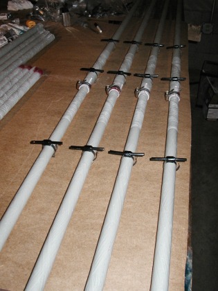 |
 |
|
| A completed set of spreaders with wire holders. |
You will have about 10 feet of extra wire on each spool when you are done stringing the elements. |
Up to this point, assembly can be done indoors. To continue, the project needs to move outdoors.
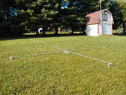
The next step is to assemble the reflector spreaders to the reflector hub (the same hub you used to measure and install the wire holders). Install each of the 4 reflector spreaders to the hub using a hose clamp. When doing this step, place the hub with the tubular end down before installing the spreader. Rotate the spreader on the hub until the wire holders are up and parallel with the ground, then tighten the hose clamp. When the clamp is tight, you should not be able to rotate the spreader on the hub. Repeat this step for the other 3 spreaders. When you are done you should have a completed spreader to hold the reflector elements.
 |
 |
|
| A completed spreader ready to install five reflector loops. |
Spreaders are attached to the hub with hose clamps. |
 |
 |