Home Links Contact Information
Copyright � 1995 - 2021 John Tait All rights reserved.
Remote Antenna
Switching
Why Remote Switching??
My original Remote Antenna switch was made specifically to select the various driven elements on my Quad. This works extremely well, and was simple to build. I then realised that remote switching for all of my antennae would have a number of advantages.
- A large reduction in the number coax "runs" from the shack to the various antenna locations, thereby making a considerable saving in cost, and complexity, of switching antennae from the shack.
- A few runs of expensive, high quality "hard line" coax to the main antenna switching points outside the shack, is CHEAPER than running seperate runs of RG213 or similar, to each individual antenna all the way from the shack.
- If an electrical storm heads in your direction, it is comparatively easy to unplug two or three coax lines and control cables and throw them on the lawn before you hide under your bed..!!! Also, all unused antennae have their coax feeds shorted to ground at the remote switch boxes.
- It is easier to experiment with new, or temporary antennae, as you can hook into a spare point at a remote switch, rather than run a temporary coax all the way back to the shack...And of course, "temporary" set-ups have a nasty habit of becoming permanent "eyesores"...
- There is an overall reduction in general"clutter" in the shack, making operating easier, and perhaps even earning the coveted "XYL seal of approval"...
There are two disadvantages to "Remote Switching"
- The cost of the switches....Negligable, if you build them yourself.... We're Experimenters....Right???
- If you lose your electrical supply to your home, in a storm, or for other reasons, you have no control of your antenna selection.
As regards the second scenario, I have always made a point of having an emergency supply available. I have a standby 3KVA generator, and also a bank of four large 12V automobile batteries wired in parallel. All my remote switches use 24V DC relays, so I series a small 12V battery with the other four to give me my emergency 24v supply. I have no preference for 24V relays over 12V relays... I use 24V relays, purely because I have a good supply of high quality relays which just happen to be 24V...
If you have a small antenna setup, with perhaps a tribander, and a Zepp, or trapped vertical for the lower bands, then remote switching is not really any advantage. If on the other hand, you're one of the lucky ones, and have lots of space for lots of antennae, then you should probably take a look to see if it can be of advantage in your situation.
In my own case, (I'm one of the lucky ones) I live in the country, on the coast, and my site is approximately 1/2 an acre. I have permission from my farmer neighbours to erect whatever antennae I like, in the surrounding fields, so long as I do NOT interfere with the agricultural activities in any way whatsoever. I have erected four large (45-60ft) timber poles at various locations on the boundaries of surrounding fields. I have a 55ft tower at the back of the house, and a couple of verticals in another corner of the garden. I have a 4insOD plastic conduit running underground from the shack to the tower...120ft. Another conduit to the Verticals about 80ft. But the run to the 60ft pole in the field is 900ft...Yes ...nine hundred feet..
I run three coax lines to these locations, and have one or more remote switches at these three antenna sites. For instance, at the tower, one coax line feeds the eight bands on the Quad (40M thru' 6M) and a sloper..Nine antennae...One coax...one control line.
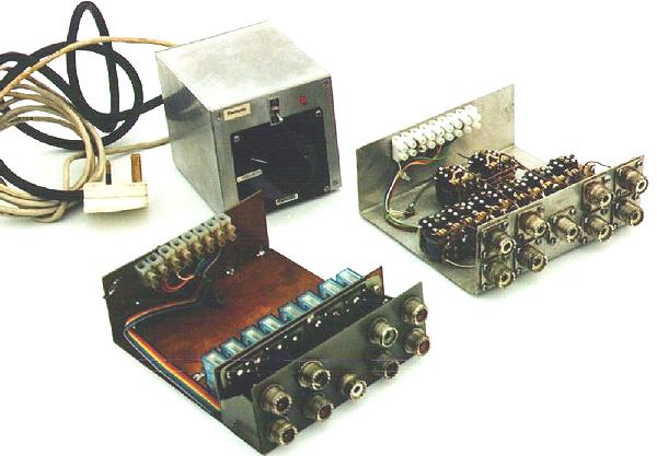
Simple Remote Switch..
The switch consists of two units, the control switch in the shack, and the relay box at the remote end. The Control Box consists of a small Power Supply providing 12V or 24V DC to suit whatever relays you are using. The " + " of the DC supply is connected to the input of a rotary switch, and the output tags of your switch are wired to a terminal strip mounted on the back of the box. A multi-core cable is then run from the terminal strip to the Remote Relay Box at the antenna site.
( Diagram of Remote Relay Box.. All unused antenna outputs are grounded)
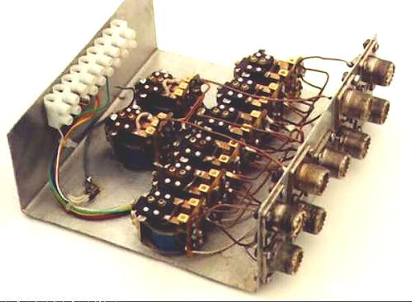
Most of the surplus relays that I come across are encased in a clear plastic cover, and have " OCTAL" bases. Others have flat metal "pins".Anything that can handle about 240V AC, at about 10Amps, should be adequate for powers of up to 1.5kW of RF. ( switching 50 Ohm coax).
You can use these "as is", soldering the wiring direct to the pins on the bases of the relays. I prefer to modify my relays, because the long connecting wires from the base to the switching contacts, are usually pressing against the relay bobbins. This must induce RF into the bobbins, and probably introduce a bit of distruption to our 50 Ohm line. I remove the bases and plastic covers. I also remove the "flying leads", and solder a jumper between the two relay switching "leafs". This shortens the RF path through the relay,and reduces any extraneous coupling. Hopefully the drawing below will be adequate explanation of the modification...
( Pic of remote relay switch box, with modified relays)
The MK2 Switch Box
Recently, I got some really nice new modern PCB mounting relays. They are quite small and tidy, but the bobbins are well away from the contacts. The Contacts are silverplated, and are rated to handle about 2kW at 240v AC. The use of a PCB, really tidies up the wiring., and minimises anomolies in the RF path... See pics below... The local contest station EI7M, recently used this switch in "battle conditions", and hopelessly failed to do any damage to it....C'mon guys... Your not TRYING!!!!
( FINDER type 40.31 S . PCB mounting 24V relay. They measure 1ins high by 1ins long by 1/2ins wide..approx )

( Pic of relay box using PCB mounted relays, and PCB board chassis)
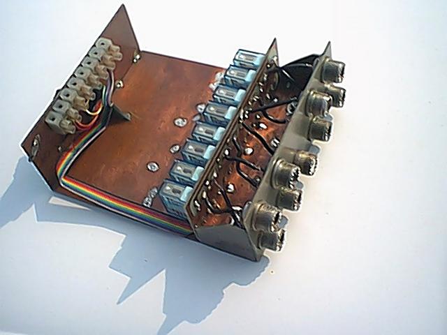
(Rough drawing of PCB layout)
Home Links Contact Information
Copyright � 1995 - 2021 John Tait All rights reserved.
All pages and content there-in, are the intellectual property of the author, and protected by law.
All pages and content, are subject to change at any time, without notice.