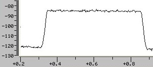
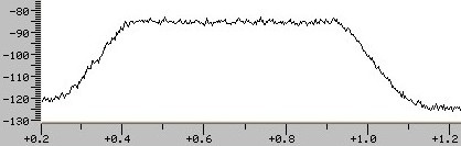
| Typical 500 Hz CW filter passbands | |||
|---|---|---|---|
| BPF | Non-BPF | ||
 |
 |
||
In July 2000, I sold my IC-756, and bought a 756Pro from a local dealer. I am delighted with the Pro. I find the Pro a big improvement over its predecessor, the 756. The Pro receiver seems much quieter than that of the 756 - probably due to a cleaner DDS LO implementation.. The DSP IF filters have much steeper skirts than the analogue crystal filters in the older rig, and are much more effective against adjacent-channel QRM than analogue filters. George, W5YR's IF Filter Page dramatically illustrates this point. Also, read George's "Notes on roofing filters" (below).
The manual pre-AGC IF notch filter (70 dB deep) is dynamite. It makes an S9+20 undesired tone disappear off the S-meter. The DSP-IF filtering, including a tuneable notch filter, is all inside the AGC loop (unlike the IC-756). The combination of the DSP-NR and noise blanker renders night-time 40m listening much more pleasant and less fatiguing. I observe significant artifacts under strong-signal conditions only when the noise blanker is enabled. These are clearly due to the NB gating on signal peaks, and are eliminated by switching the NB out.
Overall, the Pro pulls the "weak ones" out of the noise noticeably better than the 756 (or any of its other predecessors in my shack) did. The measured sensitivity on 20m with Pre-amp 1 on, and 500 Hz bandwidth, is 0.1 µV for 10 dB S+N/N (using an HP 8640B generator). I am able to copy easily SSB signals which do not move the S-meter. Those signals would have been barely intelligible on the 756. The ability to tailor the filter passband to the received signal (using the Twin PBT or the filter tables) also provides a superb tool for pulling out the "weak ones". The manual notch is also helpful in improving the SNR of the received signal.
With the Pro, you can optimise the IF bandwidth by tailoring it to the occupied bandwidth of the received signal, thus yielding optimum S/N ratio. Also, the DSP IF filters are inside the AGC loop, so strong signals outside the DSP filter bandwidth will not swamp the receiver. The fact that all the DSP IF filters, including the Manual Notch (but excluding the Auto-Notch) are inside the AGC loop sets the Pro (and the late, lamented Kachina 505) apart from all other amateur HF transceivers on the market.
The vertical sensitivity of the 756Pro Spectrum Scope is significantly higher than that of the 756. A signal of less than 1 µV is visible, whilst the 756 requires at least 20 µV to produce a spike. The only alignment procedure for the IC-756Pro spectrum scope is vertical (amplitude) alignment and calibration. The horizontal (frequency) display is in the digital domain, and thus never goes out of cal. The CAL control on the lower right side of the chassis will center the marker correctly. Incidentally, you can observe the spectral content and occupied bandwidth of your transmitted signal by setting "Scope during Tx = ON" in the "Scope Set" menu.
The transmit speech amplifier of the Pro has a little less gain than that of the 756, requiring a slightly higher MIC GAIN setting when using a Heil microphone with a dynamic insert (HC-4 or HC-5). The new Heil HM-i electret will fully drive the Pro with Mic Gain at around 9 o'clock.
The infinitely-variable DSP IF filters have far better shape factors than classical analogue filters. The tuneable IF notch filter is 70 dB deep. And once you have got used to the spectrum scope, you will never wish to be without one again. The AGC voltage is also derived from the DSP.
The IC-756Pro and an Icom amplifier - PW-1, IC-4KL or IC-2KL/AT-500 - make an excellent combination; the amplifier tracks the radio. The Pro can also be interfaced to a Yaesu Quadra. My first impressions of the Quadra are documented here.
The IC-756Pro/Pro II Monitor is excellent. A sample of the 36 kHz analogue transmit IF at the output of the main DAC is down-converted to baseband in a mixer whose LO is the 36 kHz ADC/DAC clock. The resulting audio is fed to the speaker/headphone output and the accessory audio output (ACC1 Pin 5). At the sampling point, the IF parameters are those of the transmitted signal; the next step in the main signal path is the analogue up-conversion and power-amplification chain.
Using the Monitor and a good pair of headphones, you can set up the Pro for the desired transmit audio quality with very little trouble. Try switching between NAR, MID and WIDE TX occupied bandwidth. View George, W5YR's IC-756Pro Monitor page.
The recommended microphone for the 756Pro is the Heil HM-i. The HM-i is plugged directly into the front-panel [MIC] socket. 756Pro Settings: [MIC GAIN] at 9 o'clock, Treble +5 dB, Bass -2dB, compression OFF and Tx occupied bandwidth = MID (COMP OFF MID). No auxiliary equipment is interposed between the microphone and the radio. If compression is used, set COMP ON MID, and adjust [COMP] for 5 to 10 dB compression, no more. This will avoid overdrive.
In May 2002, I purchased an IC-756Pro II at the Dayton Hamvention. Upon returning home, I installed the Pro II in my station and began evaluating it.
One week later, I can report that the verdict is very favourable. I have been using the Pro II, and have observed quite an improvement in the receiver performance compared to the Pro. So far, I have noticed superior strong-signal handling, DSP IF filtering and DSP noise reduction (NR).
The adjustable noise-blanker (NB) threshold is also a big advantage over the fixed NB level in the old Pro. I find that by increasing the NB threshold from 50% (default) to 75%, I can almost completely eliminate local HV power-line noise.
The improvement in strong-signal handling on the IC-756Pro II is dramatic. My nearest ham neighbour is 1 km down the street from me, and has a 3-element quad at a height of 18m. When he transmits SSB on 20m with approximately 1.2 kW PEP (S9 + 60 dB at my QTH), the peak values of received artifacts are as follows:
| Offset kHz | Strength | Scope |
|---|---|---|
| 10 | S5 | +40 dB |
| 15 | S3 | +20 dB |
| 20 | S2 | +10 dB |
| 35 | S1 | +10 dB |
Front-end settings for this test are Preamp OFF, ATT off, RF Gain 12 o'clock. Spectrum Scope settings are Span 12.5 kHz, ATT off. For offset > 20 kHz, the artifacts are barely audible, and do not degrade the intelligibility of weak SSB signals (S1 ~ S2), despite the increase in scope "grass" level due to this powerful signal.
By contrast, my neighbour's transmissions overloaded the IC-756Pro front end so severely as to render the entire 20m band unusable.
The Manual Notch is at least as good as that of the Pro. The Auto-Notch is more effective in suppressing multiple tones, and the received audio seems to me to be totally free of DSP artifacts and "munge". There was occasionally a barely-perceptible trace of such artifacts in the Pro. Note: The Auto-Notch is not selectable in CW mode, as it would function to notch out the very CW signal that one is trying to receive. This applies to the IC-756Pro and IC-756Pro II.
The Manual Notch can also be effective in removing the most disturbing component of a complex interfering signal. During a recent sked on 15m with my friend Matt KK5DR, a band-limited noise spectrum about 2 kHz wide popped up on our frequency at about S9. Matt's signal at that time was running S6, and the interference obliterated it. By engaging MN and adjusting the Manual Notch control, I was able to pull Matt's signal right back out of that stuff with optimal articulation and 100% copy. I defy any analogue radio to emulate this.
Using the Twin PBT with the 250 Hz CW filter selected, one can crank the CW IF filter bandwidth down to 50 Hz (as in the Pro). The CW Pitch control will not put the CW signal out of the IF filter passband, even at 50 Hz bandwidth.
George, W5YR's notes on close-in strong-signal handling:December 2002: Although my experience with my new Pro2 is limited to a few weeks, its front-end performance compared with the original PRO has been greatly improved. I cannot recall ever having to use attenuation with the PRO although I normally used Preamp 1 most of the time. With the Pro2, I have yet to use the Preamp or attenuator. The Pro2 front-end is really that much better than that of the PRO. My experience with the original PRO dates back to September 2000. I can copy an S2 CW signal less than 100 Hz from an S9+30 dB signal using a 100 Hz filter setting. There is no evidence of desensing or cross-modulation from strong signals on the band. I think that Icom has figured out how to make near bullet-proof front-ends and with their licensing of the Rohde & Schwarz front-end technology, things can only get better. I agree with comments by other reviewers to the effect that a 2002-era radio should not require manual attenuation to prevent overloading, and my experience is that the 756PRO series does not. January 2003: Concerning the ability of Icom receivers to deal with close-in strong signals, I am happy to report that the Pro2 does a better job of that than I ever expected. This parallels Adam's experience with his Pro2. My experience with the strong local station at my QTH closely mirrors Adam's, as well as our parallel tests of injecting weak signals near the calibration signal and strong signals near weak signals, etc. I can copy very weak signals almost within the same filter passband as an S9+40 dB signal. When I tune out the main response to the strong signal, the weak signal remains with no desensing or cross-modulation or other ill effects that I can identify. This behavior is clearly superior to that of the PRO. I have a "contest" local station about a mile away who runs S9+60 dB when he is on. Heard him on 40m CW the other evening and found that with no attenuation or other measures, I could copy weak signals within a few hundred Hz of his frequency. With the original PRO, he would have taken out half the band. Last night (January 9, 2003), I had an S9+60 dB AM signal on 75 metres, and I could copy an S3 SSB signal about 2 KHz away. I was getting a lot of buckshot and splatter from the AM signal, but it was not sufficient to desense or otherwise compromise the SSB copy. This is the best test I have had of the Pro2 thus far. November 2003: It seems to me that Icom thoroughly assessed a wide range of operating environments for the IC-756PRO2 and family, and determined a combination of AGC parameters, both analog and digital, that best served the cause for each case. These parameters were then locked into silicon, and operator-accessible AGC decay-time adjustments made available via the AGC menu. Results:
It is beyond dispute that Icom's engineers have designed a "real" front end! Recently, I compared the Pro2 against a popular analogue HF transceiver on 40m CW with my "1kW-plus" contester neighbor a mile away on the CQ WW CW contest. When KV5R was on, he completely pinned the meter! Using no attenuation or RF Gain reduction, I found that with a 200 Hz IF filter bandwidth and MID AGC, I could copy an S5 signal within about 2 kHz of the monster signal with only keying transients appearing in the background, and an S9 meter reading due to his keying transients. With the analogue radio, coming within 2 kHz of KV5R's signal produced a pinning of the S meter and the ability to just barely tell that there was a weaker signal present. The analogue rig's wider crystal IF filter simply let too much junk through, whereas the brick-wall DSP filters of the Pro2 rejected it. In my opinion, the front end was not the determining factor with either receiver. March 2004: During our 20m SSB Fox Hunt in the middle of the recent ARRL International DX Phone contest, I was astounded to find that I could copy good readable SSB with a filter setting of 1000 Hz and a negative Twin PBT offset of 375 Hz! The adjacent channel splatter was so bad that a 1000 Hz passband is what it took. I kept narrowing the passband as the QRM increased, and finally decided that 1000 Hz was as low as I wanted to go. Articulation and readability was excellent, especially on one station which had a rather restricted audio signal with lots of highs. This was a genuine 1000 Hz @ -6 dB passband. It was an SSB filter, so not as sharp as the CW BPF filters, but the narrowest I have ever used on phone. Still can't believe the sound and clarity of it all. Now, was my front end overloaded? Not that I could tell. Did I use any dBm from Heaven with the ATT button - no. Did I reduce the band-noise/noise-floor margin with the RF Gain control - no. Just plain old outstanding DSP IF filtering was all it took to read 5 and 10 watt signals in all that splattering mess. And they say the IC-756PRO2 doesn't have a front end! Hah! Bottom line: I found no basis in fact for believing that the much-touted "superior front end" of the analog transceiver placed it far ahead of the Pro2 in strong-signal performance. It is a neat little radio that works well, but it is no Pro2 by any means. Too many folks without the experience or knowledge to judge these matters look at the ARRL IMDDR3 numbers for the Pro2 and its competitors, and conclude that "the other rig" is the far superior radio. So much for numbers . . . |
Selectable filter shape factors: On SSB, the recovered audio sounds a little more "mellow" to my ear with the "SOFT" shape factor selected. On CW, the effect is more subtle. If the signal is in the middle of the filter bandpass, one will probably not notice much change. The "SOFT" CW shape factor has noticeably wider skirts than the "SHARP" setting. Try this test: Tune in a single-tone signal in "SHARP", with 250 Hz BW. Tune it off (up in frequency) until the signal disappears. Switch to "SOFT". The signal will reappear.
The CW "SOFT" setting is useful in cases of adjacent-channel interference caused by a nearby signal with severe key-clicks. The key-click sidebands are visible on the spectrum scope, but in some cases the "SOFT" shape factor will eliminate them from the recovered audio.
From my perspective, weak-signal handling appears to be superior to that of the earlier Pro. Very subjectively, I would say that the Pro II receiver is approximately "3 dB quieter" than that of the Pro. This is a function of an even quieter DDS LO, more effective DSP noise-reduction and improved DSP IF filters.
The "grass" (baseline noise) level of the Pro II spectrum scope is lower than that of the Pro. I also find the display somewhat sharper and crisper than on the earlier Pro. In addition, the white meter backlight is a bit more legible.
The transmitter seems to perform at least as well as the Pro. I have had excellent audio reports with the Heil GoldLine/HC-5.
All in all, I am delighted with the Pro II. I feel that the purchase was well worth the outlay - especially at the Dayton price! As I "put more hours" on the radio, I plan to add to these notes.
I finally sold the earlier Pro to an old friend in July 2003. It had served me flawlessly for 3 years.
The IC-756Pro II also extends the functionality of the BPF Indicator in the top line of the display beyond that of the IC-756Pro. The BPF Indicator now operates in SSB and CW modes (CW only in the IC-756Pro). When the IF bandwidth is set to 500 Hz or less via the FILTER menu, the BPF Indicator lights, and the CW shape factor is selected. When the IF bandwidth is greater than 500 Hz, the BPF Indicator is dark, and the SSB shape factor is selected. Note: This feature is also implemented in the IC-7800, IC-746Pro , IC-7400 and IC-7000, although the displays are totally different in the latter 3 radios.
If the IF bandwidth is set to, say, 600 Hz, then reduced to 500 Hz via the Twin PBT controls, the BPF Indicator remains dark, and the SSB shape factor is selected. Try this test: Tune in a single-tone signal in USB-D mode, with 500 Hz BW (BPF lit). Tune it off (up in frequency) until the signal disappears. Set BW = 600 Hz via the FILTER menu, then set BW = 500 Hz, SFT = 0 Hz via Twin PBT (BPF dark). The signal will reappear. Press DEF softkey to restore default 500 Hz filter (BPF lit). The signal will disappear again.
These two alternate methods for setting the IF bandwidth offer the operator a choice of filter shape factors for CW and the digital modes. The additional "SHARP" and "SOFT" settings discussed earlier further enhance this choice. With BPF lit in CW mode, selecting "SHARP" further tightens the filter skirts by comparison to "SOFT". In CW mode, with BPF not lit, switching from "SOFT" to "SHARP" does not appear to make any difference. The converse is true for USB-D/LSB-D (on the Pro II); switching shape factors is effective for non-BPF, but not for BPF.
| Typical 500 Hz CW filter passbands | |||
|---|---|---|---|
| BPF | Non-BPF | ||
|
|
|
||
In USB-D and LSB-D modes, the IC-756 Pro II FILTER menu now presents the three CW filter choices, 1.2 kHz, 500 Hz and 250 Hz. The 500 Hz and 250 Hz filter settings default to the CW shape factor (BPF Indicator lit), although the SSB shape factor can be selected as described above. This improvement in the SSB digital-mode filter selections renders the IC-756Pro II ideal for PSK31 and other narrowband digital modes.
In February 2003, I tried out various 100 Hz CW filter settings on my IC-756Pro II. The following table shows the results:
| IC-756Pro II CW Filter On-Air Test. Conditions: BW = 100Hz, SFT = 0, Pitch = 600Hz | ||
|---|---|---|
| BPF Indicator | Shape Factor | Results |
| ON | SHARP | Good single-signal copy of an S5 CW signal, slight ringing (aggravated by power-line noise spikes). |
| ON | SOFT | Good single-signal copy of an S5 CW signal, less ringing. |
| OFF | SOFT | More pleasant single-signal copy of an S5 CW signal. Softer sound, almost no ringing. Adjacent-channel rejection noticeably inferior to settings with BPF on. |
The optimum filter settings to use in any given case are a function of band conditions and personal taste.
Interaction between BPF
Indicator and selectable filter shape factors in the Pro II:
|
Recent discussion of the received audio image in conjunction with the CW offset provided an incentive for a further investigation: What happens if the DSP-IF filter bandwidth is set equal to, or greater than, twice the difference between virtual carrier and passband centre? The investigation, and its results, are detailed here.
Q. With Dual Watch, can one send the DX station to one ear only, and the hounds chasing the DX to the other ear, and vary the volume of the two signals independently of each other?
A. In a word, not quite. As the Pro2 uses a common IF chain (including the DSP), and a common receive audio chain, for both Dual Watch channels, separate audio in L & R headphones is not possible. To provide this capability, the radio would need two independent IF chains, each with its own ADC, DSP and DAC. This would have a major impact on the price of the radio. Icom's product-management people probably felt that the demand would not justify the increased cost.
Dual Watch permits reception of two signals in the same mode, IF bandwidth and band (the B channel can be in an adjacent band e.g. A on 20m and B on 17m without too much loss of sensitivity). When combined with Split, Dual Watch enables the operator to maintain a "listening watch" on the distant station's listening (receive) frequency. This is very useful when working a DX station which is operating split. The operator hears both signals mixed at the common receiver audio output. The relative A and B signal levels are adjusted via the BAL control.
Additional notes on Dual Watch are presented here.
In the IC-756Pro, there are 330Ω resistors in series with the tip & ring leads of the front-panel [PHONES] jack (one resistor in each lead). The corresponding values for the IC-756 and IC-756Pro II/III are 100Ω and 180Ω, respectively. As a consequence, the headphone level will be approximately 10 dB lower on the Pro (or 5 dB on the Pro II/III) than on the 756 (with 8Ω phones).
You can increase headphone volume by using higher-impedance headphones, by connecting a 2:1 or 4:1 (turns ratio) step-down audio matching transformer between the phone plug and the headphones or (least desirable of all) by disassembling the radio and changing out the resistors (R1 & R2 on the PHONE board).
There appears to be a misprint on pages 12 and 16 of the IC-756Pro user manual. The manual shows the left-most RCA socket on the rear panel (1) as RX ANT, and the socket to its right (2) as XVERTER. On the radio, the reverse is true; (1) is marked X-VERTER, and (2) as RX ANT. This error was finally corrected in the IC-756Pro II user manual, 2nd edition, A-6072H-1EX-(2), and in the IC-756Pro III user manual.
(Contributed by George, W5YR)
Press and hold the METER button for 2 sec. The digital bar-graph meter scales will appear in the space normally occupied by the Spectrum Scope. RF power output is shown on the top bar. When the RF POWER control is set such that the first two bars are lighted, the RF output is 5W. There is a slight hysteresis in the bar graph; it increases from 1 to 2 bars at 5W, and decreases from 3 to 2 bars at 5.5 to 6W.
The netting procedure on the IC-756Pro and Pro II is very straightforward. Here are five methods:
1: In BK-IN FULL or SEMI, depress the Morse key, and note the sidetone pitch. Then unkey, and tune the received signal to the same pitch.
2 (from John Rippey, W3ULS): Select 100 Hz CW filter. Tune desired station to centre of filter passband. Depress Morse key, and note sidetone pitch. Then unkey, and tune the received signal to the same pitch. The 100 Hz filter eliminates the signals of many of the other stations which are also calling the desired station.
3 (Most accurate): Select BK-IN OFF, depress the Morse key, and tune the main VFO knob to zero-beat the sidetone to the received signal. Then select BK-IN FULL or SEMI as desired.
The receive and transmit frequencies will now be exactly equal.
4 (Visual method): In SCOPE/SET, activate "Scope on during Tx". Select SPAN = 12.5 kHz. Tune the received signal so that the peak of the spike is on the scope centre line.
5 (from Jim Shaw, WA6PX): Press and hold the CW/RTTY button for 1 sec. to switch to CW-R mode. Verify that the pitch is the same as for CW mode. Tune the main VFO knob as needed, to equalise the pitch. Then switch back to CW mode.
The receive frequency will now be within a few Hz of the transmit frequency.
Note 1: On the IC-756Pro/Pro II, the transmit CW sidetone tracks the CW PITCH control. However, the transmit offset is fixed at 600 Hz, and does not change as the Pitch control is varied. (IC-756Pro2 user manual, p. 29).
Note 2: The default CW Pitch setting (12 o'clock) is 600 Hz.
(Based on recent comments by George, W5YR)
All the radios in the Icom Pro family suffer from this deficiency. As a function of the radio's overall receive/transmit transition time, the leading edge of the first code element following Rx/Tx switchover is truncated (clipped) by approximately 10 mS.
This truncation affects the initial element in semi-break-in operation. In full break-in (QSK), every element is clipped. The effect is most disturbing at sending speeds significantly above 20 wpm. The problem is negligible to minor at speeds up to around 20 wpm. Above that speed, the dits begin to sound a little light; by 30-40 wpm, they are clearly far out of balance with the spaces.
A definitive "fix" calls for the CW logic to continue to send each code element for about 10 mS after the key is opened. That is what an external keyer such as the Logikey does. Several CW operators have successfully used the Logikey in conjunction with the IC-756Pro II as a work-around for this issue.
Update (May 2005): This defect has been corrected in the IC-756Pro3.
A small group of IC-756Pro owners, including myself, have confirmed that under certain special conditions a low-frequency rumble appears on the external speaker output. This rumble is at a very low level, and is completely masked at normal listening levels.
The apparent cause of this rumble is a low-frequency ripple which the NB superimposes on its own +8V supply rail. This +8V rail also powers low-level audio stages following the DAC. There is a suspicion that the ripple is modulating these stages.
A "fix" for the rumble has just been published. Read "The Icom 756PRO - A Cure for the Rumble", by Tony Brock-Fisher K1KP and Jim Jarvis N2EA. This article appears in "Technical Correspondence", QST, June 2002, page 68. Read a condensed version of this article.
It is entirely possible that other artifacts observed by some IC-756Pro users are due to inadequate opposite-sideband suppression at the transmitting station. With some operators "tweaking" the carrier set point in the quest for "hi-fi" audio, there's a lot of that going around these days - not to mention degraded carrier suppression. Fortunately for the rest of us on the bands, the IC-756Pro has no carrier set point adjustment, as the DSP performs all modulation tasks. (By the way, the 756Pro also generates mathematically near-perfect AM, FM and CW signals, as well as "textbook" SSB. If you have access to a spectrum analyzer, you can check that out.) Read "Notes on Carrier Set Point and the IC-756Pro" (below).
Note on residual speech-amplifier noise, March 2003:
There has been some recent reflector discussion on this topic. One correspondent wrote: "There is a small amount of white noise with the mic disconnected and the mic gain wide open, the compression on, and the compression wide open. Connecting the mic shows that the mic pickup from the background is considerably more noise than produced internally in the radio. The internal noise in the rig is insignificant unless one desires to whisper into the mic and have full output power."
To verify this, I ran a test on my IC-756Pro II. Transmitting at 28.5 MHz USB, with a 10W 25 ~ 60 MHz Bird element and the mic unplugged, I noticed no deflection on the power meter with Po set to 100W, for any Mic Gain and settings with Comp on or off. (TX BW = MID for all tests). However, I did observe a 5 dB spike on the Spectrum Scope with ± 12.5 kHz span.
I then ran the same test at 14.1 MHz USB using an HP 853A/8558B spectrum analyzer. With 100W = 0 dBc reference on the analyzer screen, I observed the following: (TX BW = MID)
Mic Gain at 0%, Comp at 50%, Comp off: -75 dBc spike at 14.1 MHz
Mic Gain at 0%, Comp at 50%, Comp on: -65 dBc spike at 14.1 MHz
Mic Gain at 50%, Comp at 50%, Comp off: -65 dBc spike at 14.1 MHz
Mic Gain at 50%, Comp at 50%, Comp on: -55 dBc spike at 14.1 MHz
The -6dB occupied bandwidth of the observed spike was approx. 3 kHz.
The spike appeared to contain low-frequency products (possibly AC mains harmonics.) It did not look like phase noise. I did not perform a full-blown phase-noise test, but the transmitted composite noise at 100W output in RTTY mode appeared to be below the threshold of my test lash-up.
The spike described above appears to be due to "garbage" picked up by the unterminated speech-amplifier input modulating the transmitter. In any event, the observed power level is considerably less than the 2W observed by an earlier correspondent. For the worst-case measurement (4), -55 dBc = 55 dB below 100W = -5 dBm = 0.3mW.
With Mic Gain at 0%, I could not hear any rise in noise floor on a nearby Sony ICF-SW7600G portable receiver with Comp off or on. Increasing Mic Gain to 50% with Comp off raised the noise floor on the portable slightly, and a little more with Comp on. The portable was 50 cm away from the dummy load.
It is safe to conclude that with the speech-amplifier input correctly terminated by a low-impedance microphone, the ambient noise input will be considerably in excess of the residual noise.
Notes on the Digital Voice Recorder (DVR) feature, May 2003:
Q: Is it possible to configure the DVR to retransmit audio clips previously recorded over the air?
A: In a word, No! According to information received from Icom Japan, no variant of the IC-756Pro or Pro II offers this capability. There is no "secret mod" either. The DVR can only retransmit audio previously recorded via the microphone.
Icom Inc. in Osaka has officially stated that over-the-air playback of traffic recorded off-air on the IC-756Pro/Pro II voice-recorder function is not possible in any version of the radio.
Note on AM operation with the IC-756Pro or Pro II:
The DSP modulation process in the IC-756Pro or Pro II generates a mathematically near-perfect double-sideband AM signal. The Spectrum Scope greatly simplifies AM setup. (Before starting, select "Scope ON during Tx" in the Spectrum Scope menu.)
To set the Pro or Pro II correctly for AM, key the transmitter and set [RF POWER] for 25W resting (unmodulated) carrier output (see box below). Then whistle into the microphone, and adjust [MIC GAIN] so that the peak sideband amplitude is exactly 6 dB below the carrier amplitude, as displayed on the scope. The transmitter is now correctly set up for AM operation.
The transmitted occupied bandwidth (TOBW) in AM mode is approx. 5.6 kHz. The following receive IF filter bandwidths are available: 9, 6 and 3 kHz. The inner Twin PBT knob functions as an IF Shift control. The Compressor [COMP] is disabled in AM mode.
Q: Why 25W in AM mode, rather than Icom's 40W setting?A: I recently measured the carrier-to-sideband amplitude relationships in AM (A3E) mode on my IC-756Pro II, using an HP853A/8558B spectrum analyzer. With fc = 7150 kHz, and fm = 1 kHz at a modulation level such that both sidebands are 7 dB below carrier (90% modulation), I checked the carrier amplitude variation between 0% and 90% modulation at 25W and 40W resting carrier output. The results were as follows:
The observed 3 dB decrease in carrier amplitude at 40W resting carrier and 90% modulation indicates ALC action to maintain the 100W PEP power budget of the PA. At the same time, an increase of approx. 5 dB in the amplitude of sidebands at 2fm, 3fm etc. was seen, indicating distortion of the modulation envelope due to the "starved-carrier" operation at 40W resting carrier. Apart from this increase in harmonic distortion, AM operation at 40W does no harm, as the ALC limits the PEP output to 100W (the design rating of the IC-756Pro II PA). The above measurements support my recommendation to set AM resting carrier output to 25W (rather than 40W, as specified in the IC-756Pro II product literature). The value of 25W is derived from the power relationship between the carrier and sidebands in an AM (A3E) signal. At 100% modulation, composite PEP (carrier and both sidebands) is 4X resting carrier power. Thus, for 100W PEP, the carrier output should be set to 25W maximum. Q: How do I set up my IC-756Pro II/IC-PW1 station for AM? A: Perform the following steps:
If you set the PW1 output too high, the ALC will level the output to 1kW on modulation peaks, and upset the 4:1 ratio of resting-carrier to PEP output. This will cause carrier starvation and distortion, as discussed above. Q: Can you explain the amplitude-sensitive digital artifacts which appear on the transmitted AM signal? A: With any system involving A/D and D/A conversion, quantizing distortion will occur at high signal levels. This will manifest itself as noise on modulation peaks. As the ADC and DAC used in the Icom radios are 24-bit devices originally intended for high-grade audio applications, quantizing distortion will be insignificant as long as the devices are not overdriven. Note that as the analogue input level to the ADC approaches the "all 1's" point, quantizing distortion will increase sharply. If [MIC GAIN] is set for 90% modulation, using the Spectrum Scope as described above, the ADC will remain well within its linear range. Also as discussed above, Po must not exceed 25W resting carrier. The spectrum-analysis test (described above) yielded a clean display, without visible artifacts. In January 2007, I ran an AM listening test on my IC-756Pro3 at 25W resting carrier and 90% modulation , using a simple tuneable demodulator consisting of a military ME-61/GRC field-strength meter connected to a good-quality headset . The recovered audio sounded smooth and clean, without audible artifacts. This tended to confirm the spectrum-analysis test. |
Note on FM operation with the IC-756Pro or Pro II:
As with AM, the DSP modulation process in the IC-756Pro or Pro II generates a mathematically near-perfect FM signal. The Spectrum Scope greatly simplifies FM deviation setting. (Before starting, select "Scope ON during Tx" in the Spectrum Scope menu.)
Note: As the compression/TOBW softkey function (COMP-ON-WIDE etc.) is disabled in FM mode, the FILTER menu also selects the peak deviation when the FM mode is selected.
The DSP IDC function limits FM peak deviation to ±5 kHz when the 15 kHz FM filter is selected via the FILTER menu. To set the Pro or Pro II correctly for FM (16K0F3E) on 6m or on 10m above 29.0 MHz, select the 15 kHz FM filter in the FILTER menu, then key the transmitter and whistle into the microphone. Set [MIC GAIN] to the point where deviation just limits at TOBW = 16 kHz at -26 dBc, as displayed on the scope. (The symmetrical sideband pairs are clearly visible on the display.) The transmitter is now correctly set up for FM operation.
Similarly, FM peak deviation is limited to ±2.5 kHz when the 10 or 7 kHz FM filter is selected. To operate NBFM (11K0F3E) on the HF bands below 29.0 MHz, select the 10 kHz FM IF filter, then set [MIC GAIN] for TOBW = 11 kHz at -26 dBc using the above procedure. This will comply with FCC Part 97.307(f)(1): No angle-modulated emission may have a modulation index greater than 1 at the highest modulation frequency. The 10 kHz IF filter will also yield an improved S/N ratio on receive, as IF bandwidth now more closely matches TOBW.
I also recommend setting RF/SQL in the SET/OTHERS menu to "Auto". This will allow the [RF/SQL] control to function as an RF Gain control in SSB, CW and RTTY modes, and as a squelch in AM and FM modes.
Ref. 24 is an excellent discussion of FM in amateur radio.
It is very refreshing to see the quotation from the ARRL reviews to the effect that at HF, the external (antenna, man-made and sky noise) is many dB higher than the receiver's system (internal) noise. This is discussed in more detail here.
Recently, I measured the sensitivity of my new IC-756Pro (S/N > 2600) at 28.500 kHz, with 500 Hz BW and Pre-amp 2 engaged, as 0.1 µV (-127 dBm) for 10 dB S+N/N. The comparable figure for my previous rig, an IC-756, was 0.13 µV (-125 dBm). The signal source was a recently calibrated HP 8640B signal generator.
An examination of the RF Unit schematic reveals that the Pre-amp 1 and 2 circuits in the two radios are very similar. In both radios, Pre-amp 1 uses a pair of 2SK2171 JFET's in parallel; the two circuits are almost identical, except for RF output transformer type and a few minor differences in component values. Again, in both front-ends, Pre-amp 2 is an NEC uPC1658G MMIC. Judging from differences in connections and external component values, this device is being run in the Pro at a lower Vcc, with lower absolute power output, but slightly higher gain, than for the 756 case. This suggests a lower noise figure and better IP3 characteristics for the 756Pro case. (Refer to Pages 11-6 and 10-8 of the 756 and Pro service manuals, respectively). All of this suggests that the system noise figure will be comparable for the two transceivers.
According to the ARRL tests, the transmitted composite noise at fo + 2 kHz (fo = 14100 kHz) is -115 dBc/Hz for the IC-756, compared to -125 dBc/Hz for the 756Pro. This suggests a quieter DDS implementation in the Pro. Assuming a comparable system noise figure for both radios, it should be possible to predict better MDS (and sensitivity) for the Pro. In this light, the 6 dB difference in measured MDS in favour of the 756 is difficult to comprehend, unless the insertion loss of the RF band-pass filters is 6 dB or so higher in the Pro. It is interesting that measurements performed by some other reflector members, and by myself, tend to favour the Pro.
It is well known that the noise figure (NF) of the first stage of a receiver is a close approximation of the system noise figure, assuming substantial gain in the first RF stage and negligible insertion loss ahead of that stage. (Note: To ensure that AGC action in the presence of strong signals does not degrade system NF, the AGC gain-control point is not placed ahead of the first RF stage. Each dB of loss inserted ahead of the first RF stage increases NF by 1 dB.) So we can say that the pre-amp (actually the RF amplifier - I do wish the amateur HF industry would use that term!) sets the system noise figure. That said, the external noise will always be at least 10 dB above the system noise figure at HF. This can be seen rather graphically on the 756 or Pro, by connecting an antenna and observing the sharp rise in "grass" level on the spectrum scope.
Typically, MDS = -132 dBm at 14 MHz (preamp off, no attenuation). The typical broadband power level delivered by a resonant HF antenna to a receiver is around -120 dBm. The resultant 12dB increase in noise level upon connecting the antenna amply demonstrates the above point. The operator can exploit this 12dB margin for quieter reception on the lower HF bands.
| Note on the noise factor (and noise figure) of a chain of
two-port networks: The noise factor F of a two-port network is defined as the ratio of
the signal-to-noise ratios at the input and output ports.
F = (S/Nin) / (S/Nout) {F expressed as a ratio} Noise figure NF = 10 log10F dB Given three such networks in cascade, where F1, F2, F3 are the respective noise factors (expressed as ratios) and G1, G2 are the respective stage gains (also expressed as ratios): System noise factor Fs = F1 + [(F2 - 1) / G1] + [(F3 - 1) / G1G2] etc. System noise figure NFs = 10 log10Fs dB as before. It will thus be seen that the noise figure of the first stage following the RF input dominates the system noise figure, provided that this stage has significant gain. If the first stage has insertion loss (e.g. a passive BPF or preselector), the system noise figure will be degraded by the amount of this loss. Proper gain/loss distribution in a receiver front end requires that the gain of the RF amplifier ("preamp") be more than sufficient to overcome the insertion loss of the preceding BPF, and that the noise figure of the RF amplifier/BPF be lower than that of the first mixer. Further reading: Reference 20. Minimum discernible signal (MDS) is defined as the input power to the receiver which yields an audio output where the power in the signal is equal to the power in the noise (S + N = N + 3 dB). Thus, MDS is equivalent to the noise floor. We can convert MDS (expressed in dBm) to noise figure (expressed in dB) as follows: MDS = -174 dBm + NF + 10 log10B We can convert sensitivity to noise figure using the following formula (Reference 21): S = -174 dBm + NF + 10 log10BW + S/Ndesired where S is sensitivity in dBm (1 µV in 50 ohms = -107 dBm). Bandwidth B is expressed in Hz, and S/Ndesired in dB. (The most common value is 10 dB.) |
The "bottom line" is that small differences in NF, MDS or 10 dB (S+N)/N sensitivity amongst HF receivers will, in most cases, be swamped by the external noise - certainly on HF, and often also on 6 metres. We can all take comfort in that as we anxiously hook our new rigs up, first to a signal generator, then to our antenna systems. The sudden roar of noise, and the band of "grass" on the scope, when the antenna is plugged in, should make us feel very good about our receivers!
Note on S-meter calibration: Refer to the IC-756Pro II Service Manual, page 4-14, for the S-meter calibration procedure. A correctly-calibrated S-meter will read S9 at a 50 µV (-73 dBm) RF input level. The RF input level for S9+60 dB is 50 mV (-13 dBm). Setup conditions for S-meter calibration are: Preamp OFF, ATT OFF, AGC MID, Filter = 2.4 kHz, Frequency = 14151.5 kHz.
Note on AGC, and the AGC gain-control point:
It will be seen from the IC-756Pro II front-end block diagram that AGC voltage is applied to the 64.455 MHz first-IF amplifier (Q721) following the roofing filter. The AGC gain-control point is thus well downstream of the point which determines the system NF (1st mixer or RF preamp). This indicates that Icom's designers have ensured that the linear RF/IF stages upstream of the gain-control point are sufficiently linear (over a wide range of RF signal levels) to be run "wide open". Operational experience with the IC-756Pro/ProII has confirmed the validity of this approach. The IC-7800 employs a similar AGC scheme. With Preamp off, the AGC threshold is -96 dBm (3.5 µV). Recent measurements confirm this value. See also Reference 14.
In the IC-756Pro series, the AGC derivation point is a DSP process following the IF selectivity and variable stopband (manual notch) processes. This means that as long as the ADC is nowhere near "all-1's" (over-range) level, the AGC will respond only to signals within the passband of the DSP IF selectivity process.
If an IMD product generated upstream happens to fall within the DSP IF bandpass, it will develop AGC voltage (as long as its power level exceeds the AGC threshold.) The roofing filter will reduce the statistical likelihood that this will occur. There is a crossover point in roofing-filter bandwidth where the risk of an in-band IMD product increases, rather than decreasing, with diminishing roofing-filter bandwidth due to IMD in the filter and its associated circuits (driver amplifier, transformers etc.)
The -96 dBm AGC threshold was chosen such that at low RF signal levels, before any AGC is applied, sufficient IF signal power is present at the ADC input to ensure that the quantisation noise of the ADC does not degrade system NF. As the RF signal level increases above the AGC threshold, the AGC voltage applied to Q721 levels the signal power at the ADC input to hold the ADC well below the "all ones" point. This is discussed in Reference 12, pp. 4, 5.
The AGC attack time is a trade-off. If it is too long, there is a risk that a fast-rising signal wavefront or spike will over-range the ADC. As the AGC loop is DSP-derived, there will then be no AGC action until the spike disappears. If the signal is of constant level, the entire receiver will remain locked up until the signal is removed, as there is now no AGC action as long as the ADC is driven to or beyond its "all 1's" point.
Conversely, if the AGC attack time is too short, the AGC will clamp on a fast-rising signal wavefront or spike, thus desensing the receiver for the duration of the AGC hang/decay time.
The "RF Gain" control applies an adjustable bias voltage to the AGC line, thus effectively reducing the gain of the 64.455 MHz first-IF amplifier, and raising the AGC threshold. If the RF signal at the receiver input is sufficiently strong to develop an AGC voltage higher than the preset bias, the AGC will reduce the IF-amplifier gain still further. As the control does not affect the gain of the receiver's RF stage (preamp/first mixer) for the reason discussed above, the term "RF Gain" is a misnomer here.
Here is a procedure for using the band noise/noise floor margin to your advantage, so as to obtain quieter reception.
The IC-765 and IC-781 both have an AGC-controlled PIN diode attenuator between the RF BPF bank and the preamp input switch. The IC-756 series, starting with the base 756, does not use the PIN RF attenuator; these radios employ a gain-controlled 1st IF amplifier after the first mixer. The IC-736 and IC-738 have AGC-controlled IF amplifiers.
It should be noted here that PIN diodes can cause high levels of IMD products at intermediate attenuation levels; this is especially true at low frequencies. For this reason, newer designs employ a carefully-selected voltage-controlled amplifier (VCA) as the gain-controlled 1st IF amplifier.
Whilst the PIN-diode front-end AGC scheme raises the 3rd-order intercept point (IP3) by the amount of attenuation inserted, it also admittedly degrades the system NF by the same amount. Under single-strong-signal conditions, this NF degradation is not a concern, as there is C/N to spare. Now, what happens if two or more strong signals outside the IF passband produce an IMD product in the passband? If the absolute power level of this product is below the AGC threshold, it will not desense the receiver. As the 20 kHz IMDDR3 is already 100 dB or so, the two undesired signals will need to be pretty strong - around +5 dBm each - to cause the RF attenuator to desense the receiver sufficiently to cause a noticeable S/N degradation to a weak signal in the passband over and above the idle-channel noise (ICN) which the offending signals will generate in any event. Presumably some equilibrium point will be reached where the reduction in this ICN due to the attenuator will offset system NF degradation caused by the same attenuator. Perhaps this is why some commercial HF-radio manufacturers still use this form of RF AGC.
The ambient noise at a typical HF site is 10 to 12 dB above the receiver noise floor. Thus, adding 6 or 12 dB of attenuation ahead of the first mixer will reduce C/N by the corresponding amount, and bring up the receiver noise floor to the point where it is at or just below ambient "grass" level. (We discount impulse or man-made noise for the moment.) This is still acceptable, as the system NF is not yet the limiting factor in the system's ability to discern a signal just above "grass" level. This is an acceptable price to pay for a 6 or 12 dB improvement in IP3, and could well be another reason why some designers still favour front-end AGC.
To sum up: If an amount of attenuation is inserted at the receiver's RF input which reduces the input signal power whilst ensuring that the antenna noise is still above the receiver's noise floor, the system will gain at least 10 to 12 dB of "IP3 from Heaven" without compromising system NF. When a receiver is connected to an antenna, the system NF is determined by the band (antenna) noise, and not by the NF of the front end terminated in 50Ω. (We assume that the stages following the attenuator have sufficient gain to overcome the inserted loss.)
Comment by George, W5YR: Front-end attenuation is an effective means for increasing dynamic range as long as it does not compromise the NF of the receiver relative to the band noise environment, and there remains sufficient gain margin downstream to compensate.
We know that you can select a band and observe the noise level in terms of S-meter reading and audio output. Insert attenuation until disconnection and reconnection of the antenna shows, say, a 3 dB increase on the S-meter of band noise over set noise. Now, reduce the RF gain until there is just a perceptible change in the S-meter with the antenna connected. Now turn up the audio gain until the band noise audio output is the same as when you started.
Result: you have increased IP3 by whatever attenuation you introduced. You have increased dynamic range by reducing both signal and spurious inputs in the front end and in the post-mixer stages. The audio noise output of the receiver is the same as before and its sensitivity has decreased only perhaps a small amount, but this is arguable depending upon the nature of the band noise among other factors.
Truly "dBm from Heaven" by the simple expedient of changing the gain distribution within the receiver.
Why is this very basic concept not more widely known and employed? Do radio manufacturers think that it is too complex to put in their documentation?
| Comments on atmospheric noise and receiver noise floor by
Allan Kaplan, W1AEL:
(originally posted on the Ten-Tec Contesting list, Feb. 24/25, 2004). Text in square brackets added by Adam, VA7OJ/AB4OJ. Below perhaps 12 meters, atmospheric noise absolutely overwhelms the sensitivity [noise floor] of modern receivers. By that, I mean that scientific studies by CCIR [ITU-R] have shown conclusively that atmospheric noise below 25 MHz is much stronger than a sub-microvolt signal. Especially for 80 meters, it is easy to determine if a receiver has adequate sensitivity. Here is a simple test: Temporarily disconnect the antenna, and set RF Gain on MAX. Turn up audio to a convenient level of noise output. Now restore the antenna connection. On a receiver with sufficient sensitivity for HF, the audio output noise level will increase (quite a lot on 80 meters!). You have just demonstrated that the receiver hears the external noise well above its internal noise. It will be impossible to hear any signal lower than the external noise. [If you are considering the Jupiter and the IC-746Pro, the] Jupiter will easily pass this test, as should the 746 PRO. Make your choice based on some factor other than sensitivity! Performing the sensitivity test I suggest really does yield valid results for a receiver and antenna system in its environment. To the extent that location, frequency, and antenna [characteristics] may mitigate atmospheric noise, a system that has maximum useable sensitivity for the vast majority of radio amateurs might be found wanting in a very rare situation. The "antenna on/off test" pertains directly to the environment of the receiving site, [and to the antenna aperture. A small-aperture antenna will not only capture less atmospheric noise; it will also capture correspondingly less desired-signal power. Thus, C/N will remain the same; if the signal is buried in band noise on a large-aperture antenna, it will be just as buried on a small-aperture antenna. Low-gain mobile and "stealth" antennas fall into the small-aperture category.] This is not some theory-in-the-clouds notion, but a time-honored practical test with solid theoretical underpinning. |
To protect the keying circuit of the 756Pro, use an auxiliary keying relay, such as the Yaesu FRB-757A, or an small open-frame relay with a 12V coil drawing 100 mA or less. Connect a diode (e.g. 1N4001) across the coil with cathode to +12V. The relay contacts must be rated to carry the keying voltage and current of the amplifier. Here is a good example.
The ALC line should always be connected. When using a solid-state amplifier, ALC is mandatory, as it is the amplifier's first line of defence against abnormal operation. Set the ALC to limit the drive power so as to drive the amplifier to no more than its rated output. This will hold IMD3 to an acceptable level - a kindness to one's neighbours on the band. A side benefit is that of keeping the Radio Inspector happy.
The rear-panel XVERT RCA jack is bidirectional. In response to a reflector request, I measured the transverter RF drive level (in transmit) on my IC-756Pro II. Here are the data:
Test Setup: IC-756Pro II, S/N 26XX, with XVERT jack connected via coax jumper to R&S URV-Z4 Insertion Unit terminated in 50Ω resistive load. URV-Z4 probe cable connected to R&S URV-4 (Ver. 03) RF Millivoltmeter. (IC-756Pro II User Manual, p. 19).
7-pin DIN plug with Pins 6 (XVRT) and 7 (+12V) bridged via 27KΩ 0.25W resistor, plugged into Pro II ACC (2) socket to activate XVERT mode. Pro II set to 28200.000 kHz, CW mode, semi-break-in.
| RF Power Setting | XVERT Output, dBm |
|---|---|
| Minimum | -18 |
| 50% | -5.3 |
| Maximum | -1.5 |
In receive, the signal applied to the XVERT jack is routed to the RF BPF input. The transverter IF output power at this point should not exceed -13 dBm.
The ALC RCA jack is active in XVERT mode. A transverter equipped with a negative-going ALC line (0 to -4V DC output) will be compatible with the exciter's ALC jack.
I recently investigated the RTTY IF filters on my IC-756Pro2, using the internal Cal Marker as a signal source. This has led to a somewhat clearer understanding of the RTTY filters. Like all IF filters in the Pro series, these are implemented in the DSP.
The RTTY filter set ("Other digital filters", Ref. 15, p. 13) is a pre-AGC DSP IF filter, similar to the CW and SSB filters, but optimised for RTTY. I verified this by tuning across the Cal Marker and noting that the S-meter reading fell off sharply as the carrier moved down the filter skirts. When RTTY FILTER ON is set, pressing the FILTER softkey (F-4) displays the current RTTY FILTER setting, but does not allow choices. To change the RTTY filter setting, press and hold the RTTY FILTER softkey. The RTTY filter selections are discrete; the inner PBT knob functions as an IF shift. SSB SOFT/SHARP shape-factor selection is not available for the RTTY filters.
The Twin Peak Filter (TPF) is a post-AGC, post-product-detection DSP filter (loosely, an "audio filter"). When I tuned the Cal Marker across it, I heard the recovered audio level drop slightly in the trough between the peaks (2125 and 2295 Hz), but the S-meter reading did not drop correspondingly. This confirms that TPF is a post-AGC filter. TPF can be activated only when RTTY FILTER ON is set.
The IF filter set selected in RTTY mode with RTTY FILTER OFF is, in fact, the "regular" SSB IF filter set. I confirmed this by determining that the SSB SOFT/SHARP shape-factor selection works for this case. If RTTY FILTER ON is set, it forces the IF filter selection to the RTTY filter set. The abovementioned SSB settings are no longer effective. One can see this by pressing the FILTER (F-4) softkey; only the current "special" RTTY filter BW value will be displayed.
I have had my Pro a month now, and am really enjoying it. It does a far better job of pulling out weak SSB signals than the 756 did. I use the MID occupied-bandwidth setting (on the COMP soft-key; hold the key in to change NAR-MID-WIDE) with 2 dB treble boost, and 0 dB bass boost. I am using the Heil Gold-Line mike with the HC-5 and wide-range elements.
You can judge the audio quality via the Monitor function. The 756Pro monitor is excellent; it decodes the digital IF bit-stream generated by the DSP in transmit mode, and down-converts the resulting 36 kHz analogue IF to base-band. The monitor is thus a true representation of the transmitted SSB signal.
There is really no need to use any external audio processing hardware with the Pro. The three occupied-bandwidth selections, together with the boost/cut menu, offer 121 different transmit audio settings.
I sometimes reconfigure the 3 kHz SSB filter to 2 kHz for enhanced adjacent-channel rejection, in cases where the 1.8 kHz filter is a little too narrow. All IF filtering in the Pro is done by the DSP. I run the NR at about 12 o'clock, and use Pre-amp 1 most of the time (Pre-amp 2 for very weak signals). The combination of NR and Noise Blanker is very effective against impulse noise; however, strong signals cause the noise blanker to produce artifacts.
The Manual Notch is about 70 dB deep, and so narrow that it does not degrade the received audio. Manual Notch is also inside the AGC loop (unlike Auto Notch). This allows you to remove a heterodyne without swamping the receiver.
I was aware that there were some differences in BDR, IMDDR3 and other "numbers" in favour of the earlier IC-756, but I have a feeling that Icom may have gone through a rev. level change since the release of the early unit which the ARRL Lab tested. My radio is in the S/N 2600 serial number range, vs. 1300 range for the unit tested by the ARRL. In any event, I measured the sensitivity with 500 Hz BW and Pre-amp 2 engaged, as 0.1 µV for 10 dB S+N/N. The comparable figure for my IC-756 was 0.13 µV.
Operationally, by using the Twin PBT or by adjusting the filter bandwidth to match the occupied bandwidth of the signal, I am able to copy easily signals which were unintelligible on the 756. Also, I observe that the vertical sensitivity of the spectrum scope on the Pro is at least 20 dB better than that of the 756. Although 40m is quieter at night out here in the Pacific Northwest than on the East Coast, I have not observed any of the typical overload on that band with the Pro. With the 756, I occasionally heard artifacts from adjacent-channel broadcast stations on 40m.
On the Pro, one can adjust the filter to eliminate "splatter" artifacts. I also observe that the NB-NR combination is more effective on the Pro than on the 756 in eliminating repetitive impulse noise.
To my way of thinking, the architecture of the 756Pro represents a true paradigm shift; the DSP chipset does all filtering, modulation, demodulation, noise reduction, and audio processing. Even the transmit monitor is a digital loop-back from the DSP modulation process, so you are listening to the transmit IF, rather than a sample from the speech amplifier as in the earlier 756. All filtering, including the manual notch (but not the auto-notch) is pre-AGC; this eliminates swamping due to strong signals outside the IF passband. Also, there are no filters to buy!
Ah...but there are true IF-DSP's. Both the Icom IC-756Pro and the Kachina down-convert their penultimate IF (455 kHz) to a low final IF (36 kHz in the 756Pro and 40 kHz for the Kachina). The low IF is then fed to an ADC (analogue/digital converter), followed by the DSP chipset. The DSP performs all filtering, signal enhancement and demodulation tasks, including AGC derivation. A DAC (digital/analogue converter) following the DSP then converts the DSP output to AF base-band.
Perhaps a definition is in order: IF-DSP means that the DSP operates at an intermediate frequency (prior to demodulation). The exact frequency involved is not the issue here. AF-DSP means that the DSP operates at audio frequency (post-demodulation). A typical example of this is the UT-106 DSP module for the Icom IC-706 MkII/G. The only reason why IF-DSP has not yet reached the 455 kHz (or higher) IF stage in an amateur HF transceiver is the cost of DSP chipsets at higher speed levels. I am sure that some military HF equipment already has 455 kHz (if not faster) IF-DSP. As with all aspects of the semiconductor industry, it is only a matter of time before the price of such devices comes down to the point where they will show up in our HF rigs.
Another point to be made is that to prevent strong out-of-band signals from swamping a receiver, DSP IF filtering must be within the AGC loop. This is only feasible if the end-to-end group delay across the DSP (ADC input to DAC output) is sufficiently short to prevent instability in the AGC loop. We are already at this point with the Kachina and the 756Pro; DSP-derived AGC will only get better as the chipsets get faster.
In the current, popular competing HF transceiver, the AGC is derived by envelope detection of the analogue IF signal before the ADC, and the DSP is entirely post-AGC. This is rather disappointing in a newly-designed radio.
Blocking dynamic range (also called cross-modulation dynamic range) is defined as follows:
Blocking dynamic range (BDR) is the difference, in dB, between the noise floor and an off-channel signal that causes 1 dB of gain compression in the receiver. It indicates the signal level, above the noise floor, that begins to cause desensitization. BDR is calculated by subtracting the noise floor from the level of undesired signal that produces a 1-dB decrease in a weak desired signal. It is expressed in dB. The greater the dynamic range, (expressed in dB), the better the receiver performance. It is usual for the dynamic range to vary with frequency spacing.
Key Test Conditions: If possible, AGC is normally turned off; the receiver is operated in its linear region. Desired signal set to 10 dB below the 1-dB compression point, or 20 dB above the noise floor in receivers whose AGC cannot be disabled. The receiver bandwidth is set as close as possible to 500 Hz.
To summarise, the blocking (or cross-modulation) dynamic range is the level (relative to the noise floor) of an undesired signal offset 20 (or 50) kHz from the desired signal, at which the desired signal is compressed by 1 dB. Example: The noise floor is -127 dBm (0.1 µV in 50Ω). Two signal generators (desired & undesired signal) are connected to the receiver input via a combiner. "Desired" is cranked up to the point where 1 dB compression is seen, then backed off 10 dB. "Undesired" is offset 20 kHz, then turned up until 1 dB compression is seen. The "Undesired" level is +10 dBm. Blocking dynamic range is +10 - (-127) = 137 dB.
Now we consider the receiver issues which cause blocking: The first stage in the receiver's RF/IF chain to go into overload is the one responsible for the blocking. The blocking can occur in the RF amplifier (preamp), so the test is conducted with preamp off and on. Now, any stage from the first mixer, through IF amplifiers and downstream mixers, to the demodulator, can go into overload. The overall gain distribution is a significant factor in determining just which stage will hit its non-linear region and overload first.
The IC-765 had particularly good BDR (> 150 dB with preamp off). I believe that this was due to careful balancing of stage gains between first mixer, second mixer and IF chain. The 765 was a conventional analogue radio.
A DSP radio such as the IC-756Pro or Kachina 505 is a totally different animal. The limiting factor for dynamic range is the ADC (analogue/digital converter) which digitizes the IF for delivery to the DSP. The dynamic range of the ADC is determined by the number of bits per sample. One bit (a power of 2) = 2 x amplitude (i.e. 2 x voltage*), or 6 dB. A 16-bit DSP has a theoretical dynamic range of 96 dB; a 24-bit ADC, 144 dB. The 756Pro uses a 24-bit ADC and DAC (digital/analogue converter, and a 32-bit DSP. The absolute maximum amplitude which the ADC can encode corresponds to an encoded binary value of "all ones" , i.e. a hex value of FFFF (16-bit) or FF FF FF (24-bit). Note: Representation of negative values can result in maximum possible positive and negative values, rather than the positive maxima shown here.
At this point, please read George W5YR's Brief Overview of A-D Conversion and Reference 8.
In practice, dithering (uncertainty of resolution of Bit 0, the least significant bit) limits the achievable dynamic range to 138 dB - still pretty good. Thus, the receiver designer needs to distribute the gain of the analogue stages preceding the ADC so that no stage overloads before the ADC reaches it own overload point (the upper limit of its resolution). The DSP will then be fully exploited.
Note on dithering: It is possible that dithering induced in the ADC of a hybrid superhet/IF-DSP receiver such as the IC-756Pro series, IC-7600, IC-7700 or IC-7800 by the presence of noise and multiple strong signals improves the ADC's linearity. Perhaps this effect would cause the receiver to behave better in actual on-air operation than on the lab bench, where only two pure tones are present. Could this dither be the key to the apparent disparity between lab test results and actual on-air performance of IF-DSP receivers, as several of us have noted? This is an intriguing thought. |
The Pro derives its AGC voltage via a secondary DAC, which decodes the processed IF bitstream prior to demodulation (in the DSP). The AGC can do a very good job of protecting the ADC from overload; there are a few software tricks to minimize swamping by strong out-of-band signals. ADC overload is catastrophic, as the DSP now no longer has a useful signal to process.
I am not sure to what extent the conventional method for measuring BDR is valid for a DSP receiver, considering that the "1-dB compression point" may have no meaning at the ADC overload point, when the digital output abruptly ceases to represent the analogue input. Thus, the apparently "poor number" for the Pro in the ARRL test suite may not be a true index of receiver performance. This seems to be borne out by operational history, in which the Pro handles strong out-of-band signals very well - as long as the ADC is not driven to overload. (Note that as the maximum encoded amplitude value that the DSP data bus can present to the DAC is "all ones", the DAC can never be overdriven. However, the analogue circuits downstream from the DAC output must have sufficient headroom to accommodate this maximum output amplitude without distortion or clipping.)
Another factor is that the radio tested by the League was an early production unit. Usually, the ARRL purchases a radio from a dealer shortly after product release, thereby acquiring a first-run unit for test. The test suite often identifies performance issues which are corrected in the next series. This occurred with the earlier IC-756 and several other HF radios of various makes.
The final arbiter of receiver (and transmitter) performance is operational experience. The IC-756Pro has been used very successfully on a number of DXpeditions, and has performed flawlessly.
Whilst the Icom Pro line, like all radio equipment, has its faults, DSP technology for the first time provides the operator with tools to minimize the harmful effect of these faults on receiver performance.
*The input signal being digitized could be in current rather than voltage form, although this is unlikely.
George, W5YR's notes on operational vs. lab evaluation of DSP radios:August 2003: Having used an IF DSP radio since I bought the Doug Smith-designed Kachina 505DSP in 1998, and progressing through the Icom IC-756PRO, IC-756PRO2 and now adding the IC-746PRO, I have learned first-hand that one must spend time with these rigs, and with their user manuals, to even begin to use them to their full potential. These are not your Father's radios, so to speak. I operate a PRO of some sort daily and almost daily I learn something new or relearn something old. Usually it amounts to a different or better way to use some control or combination of controls to deal with some operational problem of QRM, QRN, etc. These radios are "easy to operate" in the sense that driving a modern car is easy once you have learned how and gained experience in a variety of operating situations. This brings us back to our instinctive feeling that we need to revisit traditional receiver testing methods. There is a natural human tendency when confronted with something relatively new and unfamiliar to seek comfort in numbers, preferably a single number, and seize upon "that number" as the arbiter of good vs. evil, etc. The infamous TOI number has recently been elevated to that status, and now any number of radios are being ranked and argued over because of tests made over a period of several years. My experience with my PROs has been that yes, there are some spurs when a lot of very strong signals are on the band. But my experience has also been that the outstanding DSP filters and capabilities for modifying the filters on the fly to suit receiving conditions at the moment, plus the -70 dB manual notch filter within the AGC loop, allow virtually any signal to be retrieved from the background. I routinely copy S1 CW signals with S9+40 dB signals 150 Hz away with little or no audible effect on the desired signal and, watching a real-time spectral analysis program output, see no changes in the noise/background floor within the DSP filter. As long as the interfering signal, spur etc. is not within the passband with the desired signal, the weaker signal can be copied. Therefore, I believe that instead of looking at numbers we really need to integrate the performance aspects of the entire radio and see how well we can adapt them to our particular needs before assigning rank orders to radios. We are fortunate in these times to have radios that we can adapt to OUR needs, rather than as in the old days having to adapt our operating habits and style to fit the radio. In this context, the article entitled "The third-order intercept point" by Leif Åsbrink SM5BSZ is a "must read". In this article, Leif explains why the much-touted IP3 is not a good figure of merit for a digital receiver. See Reference 9. |
In July 2000, I was at the West Coast DX Convention in Burnaby, BC, and chatted with a couple of the operators who had participated in the Radio-sport Team Championship in Slovenia earlier this month. They had run two IC-756Pro's at the DXpedition, and reported that the radios operated flawlessly. They even acquitted themselves extremely well on 40m at night, with the European broadcasters almost next door. This sentiment was echoed by one of the Kingman Reef operators, Steve Wright, VE7CT, who gave a presentation on the K5K operation at our local club last February. K5K used a number of 756Pro's, and the operators were very happy with them. They stood up under very arduous operating conditions, in a very hostile RF environment, and no contacts were lost due to unsatisfactory strong-signal handling.
In my station, I have not observed any overload, even during contests or Field Day. During K5K, I saw some nasty 20m signals, 10 to 15 kHz wide, on the spectrum scope of the Pro. I suspected cross-mod in the radio; however, an on-air check with an HP 853A/8558B spectrum analyzer confirmed that the signals were indeed that wide.
DSP is the way of the future. It offers a cost-effective way to design, implement and optimise radio designs which are as close as possible to the limit of what can be achieved theoretically. Those who continue to disparage DSP radio architecture and digital filters will eventually go the way of the proponents of the horse-'n'-buggy, the manual telephone exchange, the vacuum tube, the vinyl LP, etc. A radio such as the IC-756Pro is the way of the future; the concept can only improve as 32-bit ADC/DAC chips, and faster DSP's, become available at prices we hams can afford. A 32-bit ADC has a theoretical dynamic range of 192 dB, and will be limited by the noise floor of the receiver front end.
When you are "shopping" for a high-end HF transceiver, I would recommend that you consider the Pro. In comparing the Pro to its popular competitors, consider this; in the Pro, the DSP does everything - IF filtering, IF notch (70 dB deep!), all modulation & demodulation, noise reduction, transmit audio equalisation and AGC. The IF-processing part of the DSP (filtering and notch) is inside the AGC loop. By contrast, the competing product is just another analogue radio with limited DSP tacked onto the back end. The DSP is wholly outside the AGC loop, so the DSP filters cannot remove undesired signals before they develop AGC voltage and swamp the receiver.
And then there is the spectrum scope - difficult to do without once you have got used to it. The visual display of signals in the portion of the band that one is tuned to, or working, is a very powerful operating tool.
The inherent 6-metre coverage of the Pro is an added bonus. The receiver noise figure is excellent, and no $1000 transverters are required!
In the choice between an IC-756Pro and an IC-756, my recommendation is to get a 756Pro. Failing that, the 756 is a very acceptable alternative (or "backup" rig).
The two most significant deficiencies in the 756 which I had prior to the Pro were the lack of an IF notch filter inside the AGC loop, and the relatively poor vertical sensitivity of the scope. I had fitted the FL-222/223 narrow SSB filter combination; these filters greatly improved adjacent-channel selectivity, and tightened up the Twin PBT. The narrow filter pair is essential if you operate mostly SSB; the filters will cost $250 to $300 (new), on top of your $1200~1300 radio. Use of the Twin PBT to narrow the IF bandwidth comes with a price; the overall shape factor is degraded. Cascaded narrow filters avoid this. To ensure correct Twin PBT operation, the optional filters should have comparable bandwidths and shape factors. View the bandpass curves of popular Icom filters.
By the time you accumulate filters for SSB and digital modes, you will be close to the price of a 756Pro. And then there is the hassle of opening up the 756 to swap out filters according to changes in operating practice (e.g. mostly-SSB vs. mostly-digital).
I have found that the DSP Twin PBT in the IC-756Pro/Pro II is much more effective than the analogue PBT in the IC-756, or in my old IC-781. The 756Pro/Pro II's DSP filters have a minimum -6/-60 dB shape factor of 1.5; in practice, measurements suggest shape factors closer to 1.2. The Twin PBT controls shift the upper and lower flanks of the selected filter independently of one another without degrading the shape factor (unless a 500 Hz or narrower CW filter is selected, and the Twin PBT adjustment causes the BPF Indicator to go dark.)
In contrast to this, the Twin PBT controls in the IC-756, IC-781 and IC-775 shift the passbands of two cascaded crystal filters relative to each other and to virtual carrier. This is covered here. If the two crystal filters have identical or similar -6 dB and -60 dB bandwidths, the composite shape factor will be better than that of either filter alone with both Twin PBT controls at 12 o'clock. If either control is offset, the shape factor will degrade to that of a single filter.
In a stock IC-781, the two SSB filters (FL-80 & FL-96) are mismatched. The FL-80 has a -6 dB bandwidth of 2.4 kHz, compared to 2.8 kHz for the FL-96. Thus, the composite shape factor will be about the same as that of the FL-80 (1.6). This is perceptibly worse than the SF of the 756Pro II's DSP filters - confirming the operator's perception of the difference.
The narrow SSB filters for the IC-756 offer another example. The FL-223 (9 MHz) has a -6 dB bandwidth of 1.9 kHz and a shape factor of 1.9. The corresponding values for the FL-222 (455 kHz) are 1.8 kHz and 1.66. With both Twin PBT controls at 12 o'clock, the composite shape factor is approximately 1.4. Offsetting either control degrades the shape factor to some value between 1.7 and 1.9, depending on the amount of offset.
Originally, the -60 dB bandwidth for the 2.4 kHz SSB filter was stated as 2.8 kHz. For the 500 Hz CW filter, the corresponding figure was 700 Hz.
When I purchased my IC-756Pro in July 2000, I recall that there was an erratum sheet in the user manual. This sheet restated the -60 dB bandwidth for the 2.4 kHz SSB setting as 3.6 kHz. The -60 dB figure for 500 Hz CW was unchanged. Unfortunately, I did not keep the sheet - it went to the new owner of the radio. It is puzzling that Icom never updated the IC-756Pro brochure, service or user manual to reflect this change.
The figure of 3.6 kHz at -60 dB applies to the IC-756Pro, the IC-756Pro2, the IC-746Pro (IC-7400) and the IC-7800. This equates to a -60/-6 dB shape factor of 1.5.
The selectivity specifications appear to be worst-case values. In recent tests, the following approximate -60/-6 dB shape factor values were obtained for the 2.4 kHz SSB filter:
| Model No. | -60/-6 dB SF | Setting |
|---|---|---|
| IC-756Pro | 1.18 | |
| IC-756Pro2 | 1.27 | SSB Sharp |
| IC-756Pro3 | 1.24 | SSB Sharp |
Q. Is there any way to adjust the carrier point oscillator in the 756Pro?
A. The IC-756Pro has no carrier insertion oscillator, and therefore no set point adjustment. The DSP performs all modulation and demodulation tasks. In SSB mode, the DSP models an idealised phasing-type exciter and demodulator, for transmitting and receiving respectively. The DSP algorithms are hard-coded in firmware, and are not user-modifiable.
In SSB transmit, the frequency relationship between the virtual carrier and the generated LSB or USB spectrum is fixed. Three occupied-bandwidth settings (NAR 2.2 kHz, MID 2.4 kHz, WIDE 2.8 kHz) are available. George, W5YR's occupied bandwidth measurements confirm these values.
The WIDE transmit AF response at the front-panel MIC socket is approximately 90 Hz ~ 2.8 kHz @ -6 dB. It is possible to "stretch" the low-end response down to approx. 50 Hz @ -6 dB by applying the transmit audio at the Pin 4 of rear-panel ACC1 socket, with WIDE selected.
In receive, the IF filter bandwidth is infinitely variable, in the range 50 Hz ~ 3.6 kHz. In addition, the lower and upper flanks of the IF bandpass can be shifted by up to ± 600 Hz relative to virtual carrier via the Twin PBT controls.
The IC-756Pro and Pro II, and the IC-746Pro (IC-7400) are a "wholly different animal" compared to conventional radios. The DSP chipset is actually a fully-functional fixed-frequency transceiver operating at 36 kHz. RF/IF amplifiers, up/down converters and DDS frequency generators interface this transceiver to the operating frequency domain. In a restricted sense, this 36 kHz transceiver is a software-defined radio (SDR).
Input levels: ACC1 Pin 4 expects 100 mV rms (280 mV p-p) for full drive. The high input impedance will not load down the conventional output circuits of accessory devices; these tend to have source impedances in the 500 ~ 2000Ω range. The MIC input expects 10 mV rms (28 mV p-p) with the MIC GAIN control at 12 o'clock (IC-756Pro service manual, p. 4-10). A typical dynamic microphone has 3 ~ 5 mV output at 94 dB SPL (2.5 cm from talker's mouth).
Measurements performed by George, W5YR confirm that for the WIDE occupied-bandwidth setting, the low-end audio response is lower at ACC1 Pin 4 (50 Hz at -6 dB) than at the MIC input (85 Hz at -6 dB). These measurements also show that for the MID and NAR settings, the difference in low-end response between ACC1 Pin 4 and the MIC input is negligible. The explanation for this is as follows:
From a look at the transmit speech-amplifier circuit (IC451, a µPC5023 ASIC, on the MAIN UNIT board), there is an RC feedback network in the first stage (AMP). This network is a high-pass filter (HPF) whose -6 dB cutoff frequency is approx. 90 Hz. The HPF accounts for the steeper low-frequency roll-off at the MIC input compared to the ACC1 Pin 4 input (significant only in the WIDE setting). The second stage (VCA, voltage-controlled amplifier) has a flat response. The Mic Gain control sets the VCA gain via the MIGV line. (Refer to IC-756Pro service manual, Page 10-4.)
The design intent in this circuit is to cut off low-frequency components of the microphone output (below 150 ~ 200 Hz). These components contribute virtually nothing to articulation at the receiver, but rob transmitter power that can be more usefully employed to transmit the midband and upper frequency sub-bands which determine the articulation index at the receiver. Note that if bass-boost is applied to the microphone audio fed to the front-panel MIC socket, IC451 will severely attenuate all components below 150 ~ 200 Hz.
The AMOD (ACC1 Pin 4) input bypasses IC451 entirely. The outputs of IC451 and the AMOD buffer are summed, and fed to the ADC via the DTAF line. The design intent here is probably to pass AFSK signals injected via AMOD without distorting the frequency transitions, which have a low-frequency component. (Note: The transmit audio signal path does not feed a "balanced modulator". There is no such "animal" in the IC-756Pro or Pro II.)
Icom's engineers probably felt that this analogue solution would be more cost-effective and less risky (in terms of potential bugs) than separate, selectable DSP modulation algorithms for voice and data transmission.
Now, in the DSP, the low and high cutoff frequencies of the PSN modulation algorithm are hard-coded in the DSP firmware. This applies for all three occupied-bandwidth settings: WIDE, MID and NAR. As the audio signal path from ACC1 Pin 4 to the ADC is flat, its frequency response is determined solely by the DSP.
We have already seen from the above discussion that the audio signal path from the MIC socket to the speech amplifier (IC451) is 6 dB down at 150 Hz. In the WIDE setting, the DSP "modulator" is 6 dB down at 90 Hz.
Thus, it is possible to extend low-frequency transmitted audio response by selecting the WIDE occupied-bandwidth setting, and injecting microphone audio at line level via ACC1 Pin 4. The above caveat concerning articulation still holds true.
Note that the Mic Gain control has no effect on the ACC1 Pin 4 audio input. The reason for this is that Pin 4 bypasses IC451, including the VCA referred to above. VOX is also inactive when transmit audio is fed to ACC1 Pin 4.
Note also that the MIC input and Compressor (and the TX Tone controls on the IC-746Pro and IC-7400) are disabled when USB-D or LSB-D is selected. The IC-756Pro2 and IC-756Pro3 allow separate filter definitions for USB-D and LSB-D which can be different from those for USB/LSB. In addition, with USB-D and LSB-D, it is possible to set BPF filters with bandwidths of 500 Hz or less.
Q: Can I extend the transmit AF response beyond the 100 Hz ~ 2.9 kHz menu settings? A: It is not possible to increase the AF response of the modulation process beyond the limits hard-coded in the DSP firmware. "Force-feeding", i.e. boosting the bass or treble at frequencies lying outside the DSP's range, can drive the speech amplifier into non-linearity. This generates harmonics which mix with the mid-band speech components to yield a rich harvest of intermodulation products. These products "muddy" the transmitted audio. In extreme cases, excessive baseband input levels can over-range the ADC, with ruinous consequences for the modulation process. Excessive boost even within the low and high cutoff points of the DSP can cause intermodulation which will compromise the overall audio quality, and can ultimately also over-range the ADC. |
The term "software-defined radio" (SDR) has been bandied about rather a lot lately in the amateur community. This is a misnomer in HF radio design; as long as hardware components such as filters, amplifiers, mixers and oscillators are encountered in the RF signal path, with hardware changes required to modify some or all of their operating parameters, the radio is not "software-defined" - even if it is software-controlled. We will not see true SDR in HF equipment until a cost-effective ADC, running at the signal frequency, can be placed right at the head of the RF chain. Taken as a whole, the IC-756Pro, IC-756Pro II and IC-746Pro are not SDR's, for the reasons given above. In a restricted sense, though, the 36 kHz DSP core of all these radios is an SDR, as its operating parameters are almost entirely defined in the DSP firmware. Read "Basic Concept of Icom IF-DSP" and References 12, 13.
(Contributed by George T. Baker, W5YR. Refer also to George's Notes on Filtering & DSP.)
At the first IF of 64.455 MHz, there is a crystal 15 KHz roofing filter at the input of the IF amplifier. At the second IF of 455 KHz, a 15KHz ceramic filter follows the second mixer. This filter feeds the Noise Blanker Gate which in turn feeds a second 15 KHz ceramic filter preceding the third mixer to the final (DSP) IF of 36 KHz.
Admittedly, these are not “narrow filters” by classical analogue-radio standards. Although their primary purpose is image rejection, they are adequately narrow to ultimately prevent overload of the DSP A/D converter(s) and that is all that is required. In a linear system, the ultimate band-limiting can take place at any point provided that system operation is linear up to that point. Proper distribution of stage gains and appropriate AGC loop operation virtually ensure linearity in the PRO up to the DSP stage.
It is also of dubious merit to ascribe performance ills to a lack of "classical" narrow IF filters - i.e. typical 2.5 - 3.0 KHz IF crystal filters - in the PRO.
While it is “conventional wisdom” that such narrow filters are all to the good, despite their phase delay, uneven amplitude response and other negative effects, recall that we once had radios built to the “conventional wisdom” that two r-f amplifier stages are better than one, since “sensitivity” was the principal measure of a good receiver.
Furthermore, the properties of conventional crystal and mechanical filters have now met with such intense competition from the DSP approach that one can readily project that in a few years there will be little or no need or requirement for crystal filters since their performance will be - and already is - inferior to the DSP equivalent. Have another look at the IF Filter Page and compare. Here is a test which you can run on your PRO or PRO II to put the DSP IF filters through their paces.
Further comments by Adam, VA7OJ (December 2006):
The up-converting architecture, with a roofing filter at a first IF above the highest RF frequency, allows the designer to limit the bandwidth presented to the first IF chain and second mixer. The bandwidth of this filter is a trade-off. Its 3 dB BW must be sufficient to pass the widest emission the receiver is required to handle, but not so narrow that IMD and temperature-drift effects in the filter become a concern.
Reference 23 has revealed that the 6 kHz roofing filter in the IC-7800 degrades IP3 at 2 kHz offset by 16 dB, as compared to the 15 kHz filter. The most likely reasons for this surprising degradation are:
IMD generated in the filter;
IMD due to saturation of the IF amplifier driving the filter as a result of mis-termination caused by a sharp increase in filter Zin outside the filter passband;
both these effects in combination.
Furthermore, it can be shown that the limiting factor in close-in HF operation is more likely to be the poor spectral purity of the distant transmitter than any limitations in the local receiver. This is as much an operating and regulatory issue as it is a technical one.
| Q: Has anyone out there taken a look at the IC-756Pro II's 455 kHz ceramic filters with the idea in mind of replacing them
with better filters from Murata or other ceramic filter manufacturers? (June
2003)
A: In the PRO and Pro2 architectures, the 455 kHz filters play little or no role in providing the selectivity of the receiver. They serve only as 15 kHz-wide roofing filters. IF selectivity comes from the IF-DSP filter operations in the 36 kHz DSP core. One important aspect of roofing filters is that their passband characteristics must not be "too good", or otherwise they will impart phase distortion and cause other effects which can lower performance. Roofing filters frequently are of two-pole and four-pole design with relatively high shape factors (broad skirts). Unlike classical designs in which analogue filters provide receiver selectivity, Icom relies upon the design and implementation of the front end stages of the receiver to provide a high TOI (3rd-order intercept point) and dynamic range. The roofing filters serve only their primary intended purpose; image rejection. In a completely linear system, the selectivity required to separate signals and limit noise bandwidth can take place anywhere in the signal chain. In a real-world, almost-linear system, great care must be taken in the design and implementation of all stages prior to the ADC to prevent digital overload at that point. Icom accomplishes this remarkably well and presents in the Pro2 a receiver with a TOI in excess of +20 dBm without the use of upstream narrow roofing filters. It is arguable that the use of a narrow filter in the stage immediately following the first mixer would improve the overall front-end performance. Until the IC-7800 came out, Icom's response to the question was to use conventional 15 kHz roofing filters. The use of narrow roofing filters can relax the performance demands on the front end of the receiver to some extent, making feasible the use of less sophisticated circuitry with less expensive components, etc. Prior to the introduction of the IC-7800, only one hybrid analogue/DSP transceiver in the amateur or commercial markets found it necessary to rely upon narrow roofing filters "up front" to obtain an adequate dynamic range and relative freedom from intermodulation-product generation. An interesting analogue amateur transceiver, the Elecraft K2, uses a similar approach in which a single IF filter serves also as a narrow roofing filter in virtue of its placement in the signal chain. The IC-7800 represents a new departure for Icom in receiver architecture, with its double-conversion design prior to the DSP core and the use of a single 6 kHz roofing filter for all modes except FM. In this case, the IC-7800 evidently uses the 6 kHz roofing filter to augment the excellent front end design to obtain the superb +40 dBm TOI. But once again, referring to your original question, while there might be some minor advantage to improving the existing ceramic roofing filters, it is quite unlikely that the improvement would justify the cost and complexity. Note that the one roofing filter - there are several in both the main receiver chain and in the Spectrum Scope chain - that is of most importance is a crystal filter following the first mixer stage. A great deal is being made of the architecture using narrow roofing filters, with debatable claims being touted for the superiority of the approach. It merely represents one of several techniques for obtaining superior front-end performance in a receiver. As in all engineering efforts, the final arbiter is performance vs. cost. |
An examination of the IC-756Pro or IC-756Pro II block diagram reveals that the PRO has a 15 kHz crystal roofing filter at the first IF - immediately after the 1st-mixer output combiner.
The scope system in the PRO/PRO II is fed from the combiner output (before the 64.455 MHz roofing filter) at an IF of 64.455 KHz via a PIN diode attenuator and separate IF stages to a mixer, which with a 77.8 MHz LO, down-converts to 13.345 MHz for the scope circuitry. There are two 13.35 MHz ceramic bandpass filters in cascade in the mixer output, which feeds another mixer with a 12.89 MHz ± 100 KHz LO to produce an output which via a 455 kHz ceramic bandpass filter (CFJ455K8) drives the scope IF system. Note that all of the above circuitry for the scope operation is completely independent of the circuitry following the first mixer which drives the actual receiver IF and subsequent circuitry, including the DSP. No compromises in receiver IF design are required to support scope operation. (Note: The CFJ455K8 filter defines the scope's resolution bandwidth as 1 kHz at -6 dB.) To increase its dynamic range, the scope incorporates an internal AGC loop derived from the vertical amplitude signal.
As the IF pickoff point for the scope is also before the AGC gain-control point, neither the RF Gain control setting nor AGC action affects the vertical sensitivity of the scope.
There is a detailed description of the scope in Section 3-5 of the service manual (all IC-756Pro models).
With Preamp 2 enabled, 0 dB attenuation (RF and scope) and autotuner disengaged , the Pro II spectrum scope will display a visible spike with 0.12 µV (-125 dBm) at the antenna socket. (This was measured with a Cushman CE-31A service monitor in CW mode, calibrated against a Rohde & Schwarz URV4 RF power meter.) The radio was also in CW mode, with the 500 Hz filter selected.
that there are three roofing filters in the main receiver channel and three more in the scope channel.
that none of the main receiver's roofing filters are involved in the scope operation, since the scope operates as a completely independent receiver.
that the presence of the scope has no negative effect whatsoever on the design and architecture of the “main” channel of the receiver.
| Q: Can I configure the Spectrum Scope to display the
spectrum of my transmitted signal?
A: Yes. With spectrum scope active, press [F-5] (SET) to enter scope menu, then set "Scope during Tx" to ON. Please refer to page 3-9 of the IC-756Pro II Service Manual. Whilst transmitting, a portion of the 64.455 MHz 1st IF signal from the transmit IF amplifier output is passed through the PIN attenuator to the scope IF amplifier chain. Assuming that the stages following the transmit IF amplifier (3rd transmit mixer, RF power-amplifier chain) are driven within their linear operating region, the transmit spectral display will be an acceptably close replica of the actual transmitted signal. Using the "Scope during Tx" display, I am able to estimate the -6 dB occupied bandwidth of my transmitted signal quite accurately. |
(Contributed by George T. Baker, W5YR.)
Q. Is it desirable to "reinitialize" the NR periodically by toggling it on and off, or by momentarily pulsing the PTT line?
A. This is largely unneeded since the NR logic is only doing its job. NR in the Pro2 is a time-varying adaptive digital filtering operation which alters its response according to the statistics of the noise it encounters within the IF passband. The statistics can and do vary with time and the noise reduction algorithms react accordingly.
When first activated, NR appears to consider everything "noise" and thus lowers gain across the entire IF passband considerably giving the perception of a very quiet receiver . This can be interpreted as effective NR operation, but that is probably a premature conclusion...
As time goes on, however, the NR logic has more statistical history to work with and begins to alter its response accordingly. The actual noise within the passband that meets the rejection criteria of the NR logic continues to be suppressed while other frequency components are restored approximately to their original level.
One result is that the perceived "noise" (audio) level increases and one could conclude that the NR is no longer functioning. This may or may not be the case, depending upon the statistical nature of the noise.
I find it difficult to accept the premise that Icom failed to execute the NR function properly in the Pro2 and earlier models. If one examines the IF/audio spectral response of the Pro2 with the NR operating, the change in noise response of the passband can be seen to vary with time.
Initially the whole passband is diminished in level and then usually (per the type of noise I have locally) the low and high ends of the spectrum quickly "grow" in level while the midrange tends to diminish. The increased signal levels at the extremes of the passband appear to account for the apparent increase in audio level, which some are interpreting as a loss of effectiveness of the NR function.
As to "defeating" this effect with periodic PTT operation, one could probably simulate the same outcome by periodically decreasing the AF gain and then slowly bringing it back up. The PTT operating restores the NR logic to its original "starting" point so it begins anew "thinking" that most of what is in the passband is noise and lowering the overall response level. Continued PTT operation merely restarts the process and keeps the NR logic from reaching and maintaining its steady state response condition.
I apologize if any of this sounds negative or even argumentative - that is not my intent - but I think that efforts to circumvent the programmed operation of the Pro2 NR logic, while subjectively appealing, actually accomplish little toward improving the noise reduction capabilities of the receiver.
An interesting exercise would be to bury various signal waveforms in "noise" and to determine the S/N ratios for each as a function of time with NR activated. The final arbiter is whether NR improves S/N to make a weak signal more readable, not whether the receiver sounds "quieter" with NR activated. (IF I can ever find time, I would like to conduct such a test.)
A final note: the NR function is most effective with the wider IF bandwidths. As bandwidth is reduced, the noise statistics are changed and the NR has less to work with. At very small bandwidths, NR is essentially ineffective since even pure noise appears to be a randomly modulated sine wave whose frequency is related to the bandwidth. Using NR with a 100 Hz filter for CW produces little useful effect, for example.
Q: I only use resonant antennas. Should I enable my internal autotuner?
A: The purpose of the autotuner is to keep the PA happy by ensuring that it is always presented with a 50Ω resistive load for optimum power transfer and best linearity. (See Reference 19).
It goes without saying that the low-pass filters must also be correctly terminated in 50Ω resistive to fulfil the above requirement.
Even a resonant antenna will present precisely 50 + j0Ω to the transmitter at only one frequency. The mission of the autotuner is to ensure that the transmitter sees 50 + j0Ω over a reasonable VSWR excursion, i.e. a reasonable frequency band. Another advantage of enabling the autotuner is that it remains in the RF signal path on receive, thus providing additional RF preselection.
Q: But if I activate the tuner to match a slightly elevated VSWR, say around 1.5:1, won't the tuner's insertion loss exceed any mismatch loss in my feedline?
A: This will be true for some cases. However, it should be noted that the reflectometer at the PA LPF output (which reports forward and reflected power to the control processor) will start folding back the RF drive at VSWR > 1.5:1. This is yet one more reason for ensuring that the PA is terminated in a 50 + j0Ω load.
An interesting comparison of two approaches to DSP has emerged from a recent discussion with Bob, W4ATM. It is tempting to think of a direct-sampling RF-level DSP design such as the RF Space SDR-14 as the be-all and end-all. However, its 14-bit ADC which is fed directly with the entire MF/HF band 0.5 ~ 33 MHz, and samples at 66.7 MHz, has an ENOB (effective number of bits) of approx. 12.3. Each bit (power of 2) equates to 6 dB of dynamic range; thus, 12.3 X 6 = 74 dB dynamic range (from MDS to ADC "all 1's" point). The only analogue RF circuitry at the ADC input is a wideband variable-gain preamp followed by an LPF. (Read Reference 10, and comments by Pieter, N4IP).
A digital down-converter (DDC) following the ADC processes the digital ADC output into I/Q format, and translates the effective bandwidth down to 150 kHz (typical) within the 33 MHz band. The resulting DDC processing gain* increases the overall dynamic range by 10 log10 (33/0.15) = 23 dB. The resulting dynamic range is now (74 + 23) = 97 dB.
*Processing gain is not "gain" in the sense of amplification; it is a reduction of noise, and thus an increase in S/N ratio, due to the bandwidth reduction.
The overall dynamic range can be improved further by decreasing the bandwidth of the DDC output band segment. The limiting case is determined by the mathematical precision of the post-processor. The I/Q outputs of the DDC drive a PC sound-card via a USB 1.1 interface. The PC performs all demodulation tasks.
By contrast, the lower-cost 24-bit, 36kHz-sampling ADC used in the Icom Pro series has an ENOB of at least 20 (120 dB dynamic range). This is close to the effective blocking dynamic range of the RF/IF chain ahead of the ADC. Thus, Icom has done a trade-off; the engineers in Osaka realised that they would be better off at this stage of the game by not allowing a dynamic-range bottleneck at the ADC, and by designing the analogue RF/IF chain for a dynamic range as close as possible to that attainable in the ADC.
The direct-sampling architecture eliminates the traditional mixer, LO, roofing filter and analogue IF chain. Phase noise is determined principally by the ADC clock source. The ADC also adds a small increment to the phase noise due to aperture jitter, which the ADC data sheet gives in fsrms. With careful design, phase noise values of -140 dBc/Hz at 1 kHz offset, and -150 dBc/Hz at 10 kHz offset, are possible. These values have been achieved in the R&S EM510.
Therefore, when considering close-in dynamic range, a properly-designed direct-sampling receiver is substantially better than any conventional receiver, because its phase noise sets the limit for dynamic range.
Fast ADC and DDC IC's are becoming more cost-effective, as are post-processors with high mathematical precision. These trends may allow RF-DSP receiver designs to eclipse the current analogue front end/IF-DSP topology in a few years. However, there is still the concern that the composite power of a number of strong signals in the sampling bandwidth of a wide-band ADC will drive the converter beyond its "all 1's" point (over-ranging). Work is currently underway to address this concern by placing a bank of bandswitched BPF's between the receiver's RF input and the ADC input, to limit the RF bandwidth to which the ADC is exposed.
The following comment (from the ADAT data sheet) is significant: "The two-tone measurement procedure is generally not applicable for A/D converters , as the IP3 of an A/D converter decreases proportionally to the input signals. On the other hand, due to dithering, the IM-free dynamic range is in practical operation substantially higher than at the laboratory two tone measurement."
Dithering converts low-level IMD products into quantisation noise, raising the noise floor by a very small amount. The power in the IMD products is spread all over the sampled bandwidth. In a hybrid superhet/IF-DSP design, this increase in noise floor is of little consequence as it occurs at a high signal level.
I suspect that dithering induced in the ADC of a hybrid superhet/IF DSP receiver such as the 756Pro series by the presence of noise and multiple strong signals improves the ADC's linearity. Perhaps this effect would cause the receiver to behave better in actual on-air operation than on the lab bench, where only two pure tones are present. I suspect that this dithering is the key to the apparent disparity between lab test results and actual on-air performance of IF-DSP receivers, as noted by several friends of mine and myself. This is an intriguing thought.
Until high-resolution ADC's with high sampling rates become cost-effective at amateur price levels, the hybrid topology (incorporating a roofing filter to reduce the statistical likelihood of ADC overload by strong undesired signals) will remain in favour among amateur HF equipment manufacturers.
Icom is using ADC's and DAC's designed for use in wireless phones and DVD/CD players. The ADC used in the IC-756Pro II and IC-756Pro III has 120 dB dynamic range, compared to 112 dB for the chip used in the IC-746Pro.
| Comment by George, W5YR: Adam, I agree with your later note concerning the merit of the Icom approach vs. the SDR14 re sampling rates, bit levels, etc. It is still hard to beat Armstrong's original concept of taking everything down to a common fixed frequency for gain and selectivity. |
Rohde & Schwarz have announced the EM-510. This is a self-contained, direct-sampling HF receiver using a 16-bit ADC. A brochure is available. [mirror]
Visit HB9CBU's ADAT direct-sampling transceiver
site (in English). Download ADAT
documents. View
an ADAT presentation.
![]()
![]()
The Perseus direct-sampling SDR receiver from Microtelecom S.p.A. of Italy is taking the SWL community by storm, and is also making a significant impact in the amateur community. It features phase noise < 147 dBc/Hz at 10 kHz offset. The Perseus uses a fast 14-bit ADC preceded by an RF attenuator, a preselector with 10 switched BPF's and an RF preamp with +30 dBm IP3.
The audio DSP add-on, such as the Ten-Tec Omni V and VI series. These radios incorporated an OEM audio DSP board manufactured for Ten-Tec by JPS. Other examples are the IC-706 Mk II, IC-703 and R-75 receiver, with optional DSP module.
The limited post-AGC final-IF DSP implementation. Examples in historical order: IC-775DSP, Yaesu FT-1000MP, IC-756, Yaesu FT-1000MP MkV. In these radios, the DSP typically performs modulation, demodulation, NR, some audio filtering, TX EQ and auto-notch. The DSP, consisting of an ADC, DSP processor and DAC, is in the final IF but post-AGC. In the IC-775, and the Yaesu radios, an analogue back end is fitted, and touted as an "alternative" to the DSP. (Good marketing propaganda; the fact is that leaving the analogue circuitry in was cheaper than designing it out!) The final IF is in the range 10 ~ 15 kHz.
The "true IF-DSP" radio, in which DSP now does all IF filtering (including a tuneable notch), AGC derivation and TX compression, as well as the functions mentioned in (2). Here we have the Kenwood TS-870, the Kachina 505, the IC-756Pro, the IC-7800, the Ten-Tec RX-340, Pegasus and Jupiter, the IC-7400 (IC-746Pro), the IC-756Pro II, the IC-756Pro III, the IC-7000, the IC-R9500 receiver and the IC-7700. Other examples are the VS/Yaesu FTDX-9000, FT-2000 and FT-450. The IF filtering functions are now within the AGC loop. Also, due to advances in chip speed, the final IF is now typically 36 to 48 kHz (the earliest implementation, the TS-870, used 11 kHz).
The "RF-DSP" radio, in which the ADC is clocked at a frequency above the highest RF operating frequency, and processes the entire HF band. This approach is at the leading edge; it is dependent on the speed and price/performance ratio of fast ADC, DSP and DAC chips. Refer to Note on RF vs. IF DSP above.
The Kachina 505 uses 16-bit ADC/DAC, 24-bit processing and a DSP IF of 40 KHz. It has analogue AGC with selectable time constants, etc. plus a Digital AGC which works in tandem with the analogue AGC. The Ten-Tec product line uses 16-bit ADC/DAC. The Icom IC-756Pro, Pro II and IC746 Pro all use 24-bit ADC/DAC and a 32-bit DSP processor.
Times change, and so does the architecture and design of our radios. Conventional radios such as the earlier Kenwoods are vastly different in many respects from the PROs, the Kachina 505DSP, and even the Ten-Tec Pegasus and Jupiter. I don’t think that it is any accident that most of the really high-line commercial and military radios (e.g. Rohde & Schwarz, Rockwell-Collins, Harris etc.) have used extensive digital filtering and signal processing for the past several years.
The above article is now also available
in
Russian.
![]()
Read my IC-756Pro III User Review.
"HF Radio Systems & Circuits", Sabin & Schoenike, editors. Noble, 1998. This textbook was written by members of the Engineering Staff, Collins Divisions, Rockwell Corporation. Chapter 8 is an exhaustive treatment of DSP radio design concepts, of which this excerpt gives an example.
"The ARRL Handbook for the Radio Amateur", 2001 Edition, Chapter 18, Digital Signal Processing.
"The Scientist's and Engineer's Guide to Digital Signal Processing", by Steven W. Smith, Ph.D.
"A High-Performance Digital Transceiver Design, Part 1", by James Scarlett KD7O, QEX, July/August 2002.
IC-756Pro III vs. Pro II - a presentation given at the North Shore ARC in January 2006 (PDF)
A general discussion on radio receivers, by Leif Åsbrink SM5BSZ
Receiver dynamic range measurements, by Leif Åsbrink SM5BSZ
The third-order intercept point, by Leif Åsbrink SM5BSZ
Dynamic range observations for the SDR-14, by Leif Åsbrink SM5BSZ
Thinking of buying a "down-converting" HF rig with a mid-band 1st IF? Read this first!
Software-Defined Radio White Paper, Wipro Technologies, August 2002
Software-Defined Radio Comes of Age, NTIA, Fall 2001
"HF Radio Systems & Circuits", Sabin & Schoenike, editors. Noble, 1998, pp. 145-148 (AGC Design); pp. 341-342 and Fig. 8.10 (Digital AGC Methods). Get excerpts (PDF)
"IC-756Pro II Technical Report", Icom Inc., 2003. (PDF) mirror site
"IC-756Pro II Receiver IMD and DSP Filter Performance", by J. Saito JA7SSB, CQ Ham Radio, January 2002. Summary by N. Oba JA7UDE (PDF) Appendix (PDF)
"A History of Crystal Filters", by R.E. Kinsman. IEEE International Frequency Control Symposium, 1998.
"Intermodulation testing of high performance receivers", by John Thorpe. AOR (UK) Ltd.
"HF Radio Systems & Circuits", Sabin & Schoenike, editors, Noble, 1998, Chapter 12, .Get excerpt (PDF)
"Understanding Noise Figure" by I. Rosu, VA3IUL.
Receiver Sensitivity Metric Converter - Receiver Noise Figure, Noise Floor & Sensitivity Calculator
DSP in HF Radios - a presentation given at the North Shore ARC in February 2006 (PDF)
"Test von Intermodulationsfestigkeit" by W. Schnorrenberg, DC4KU, CQ-DL, 8-2005, p. 544. Translation
Analog-to-Digital Converter Considerations, by Andrew Roos ZS6AA.
Amateur Radio Application of Frequency Modulation, by VK1OD.
Copyright © 2000-2018 A. Farson VA7OJ/AB4OJ. All rights reserved. (Copyright in contributed items reposes with the respective contributors.)
Last revised:
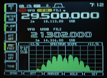