Adam, VA7OJ/AB4OJ's IC-756Pro III User Review
Initial observations (July 2005)
On June 30, I picked up my new IC-756Pro3 (S/N 32025XX) at a local
dealer. That evening, I installed the Pro3 in my station. Preliminary findings
are that it pulls weak, noisy signals out of the noise somewhat better than the
Pro2. I was able to work a number of SSB stations on 40m which I would not have
heard on the Pro2. The NR and NB appear to have been significantly improved.
Overall, I would judge that the S/N ratio is better than on the Pro2, even in the presence of
power-line noise. I find myself routinely operating with the preamp off; on the
Pro2, I invariably had Preamp 1 on.
The next day, I was able to sustain the sked
with my friend Matt KK5DR somewhat longer, as the Pro3 "hears" signals buried in
the noise somewhat better than the Pro2 did. I am able (by using a combination
of NR, NB, Twin PBT and Manual Notch) to squeeze intelligible copy out of the
assorted "garbage" on the band more effectively than on the Pro2. In addition, the Pro3's
strong-signal behaviour appeared to be excellent. S9 + 60 dB signals 1 to 2 kHz above
and below our channel edges did not produce any perceptible artefacts in the
received audio.
When switched in, Preamps 1 and 2 do not raise the audible noise level in the
receiver as much as they did in the Pro2. In the Pro3, the preamps have been
designed for highly linear large-signal handling, consistent with a low noise
figure. Preamp 1 has negative feedback to improve linearity without compromising
NF. There has also been a significant gain redistribution. The first mixer has
lower gain, with the result that the scope module in the Pro3 has its own
RF amplifier to bring up the vertical sensitivity of the
scope.
Notes on ALC
The ALC is a little less sensitive; I need to set the Quadra ALC menu to 5 bars
for 1kW output, vs. 4 bars for the Pro2.
As is the case for all other Icom HF transceivers, the rear-panel ALC jack is
compatible with a negative-going ALC voltage in the range 0 to -4V.
Positive voltage should
never be applied to the ALC jack.
In August 2007, I performed an ALC overshoot test on my Pro3/Quadra station.
Here is the test report.
There have been some improvements in operational convenience. The mini-scope is
great - you can now display 3 windows; frequency/mode etc., mini-scope and
bar-graph meter, filter menu or any other lower window that used to suppress the
scope on the Pro2. There are two clock displays - UTC and local - and a simple
screen-saver which displays the owner's callsign moving about on a black
background. By being able to leave the bar-graph meter on-screen along with the scope,
I learned that compression peaks at 6 to 7 dB when it only shows 2 to 3 dB on
the much slower moving-coil meter.
Display quality
I have the impression that the Pro3's TFT display is superior to that of the
Pro2. The screen image is brighter and a little sharper, the
contrast is much better and the colours are more saturated.
As the ARRL, RSGB and others have already subjected the Pro3 to exhaustive test
suites, I felt that any such effort on my part would be redundant (apart from
the fact that my second signal generator is much too "dirty" for meaningful RF
2-tone measurements!)
To satisfy my own curiosity, though, I ran a few quick receiver tests: MDS,
reciprocal mixing noise and filter shape factors. The test setup was as follows:
HP8640B signal generator, calibrated against R&S URV4-03 RF power
meter with 0 dB probe; Sinadder 3 configured as true RMS audio voltmeter
connected to [SPKR] jack. NB off, NR off, ATT = 0 dB, AGC MID. Offset tone pitch
= 1 kHz (SSB), 600 Hz (CW). SSB and CW "Sharp" filter shapes selected.
1: MDS (Minimum Discernible Signal). In this test, MDS is defined
as the RF input power which yields 3 dB unweighted S/N at the output. The
results obtained are very close to those in Ref.2.
Table 1: MDS (Min. Discernible Signal)
| MDS at 14.1 MHz (dBm) |
| Preamp |
SSB 2.4 kHz |
CW 500 Hz
BPF |
| Off |
-126 |
-131 |
| 1 |
-133 |
-139 |
| 2 |
-135.5 |
-142 |
2: Reciprocal Mixing Noise.
Reciprocal mixing occurs
in a superheterodyne receiver when the noise sidebands of the local oscillator
(LO) mix with strong signals close in frequency to the wanted signal, producing
unwanted noise products at the intermediate frequency and degrading the receiver
sensitivity. Reciprocal mixing noise is a measure of LO spectral purity.
In this test, a strong "undesired" signal is injected into the receiver's RF
input at a fixed offset from the operating frequency. The RF input power is
increased until the receiver noise floor increases by 3 dB. The reciprocal
mixing noise parameter, expressed as a figure of merit, is the difference
between this RF input power and measured MDS. The test is run with the 2.4 kHz
SSB filter selected, and preamp off.
The higher the value, the better.
Table 2: Reciprocal Mixing Noise
| |
Recip. Mixing (dB) |
| Offset kHz |
3.6 MHz LSB |
14.1 MHz USB |
| 2 |
80.5 |
79 |
| 3 |
83.5 |
81 |
| 5 |
88 |
86 |
| 10 |
95.3 |
91.5 |
3. DSP-IF filter shape factors. A quick check of -6/-60 dB shape
factors was performed for the 2.4 kHz SSB, 500 Hz CW and 250 Hz CW
IF filter settings. (Note:
BPF Indicator was on
for CW filters.) Shape factors for all 3 filter settings met or exceeded Icom's
advertised specifications. The measured -6/-60 dB shape factor for the 2.4 kHz
SSB filter was 1.24; the spec is 1.5.
Tip: To achieve optimum
S/N ratio, the selected IF-filter bandwidth should not exceed the occupied
bandwidth of the received signal.
4. SHARP vs. SOFT SSB filter roll-off. Test conditions:
10.000 MHz LSB, 2.4 kHz filter selected, RF input power -103 dBm (below AGC
threshold), AGC off, preamp off, ATT = 0, NR off, NB off, Twin PBT neutral.
Table 3 shows the roll-off for the [SHARP] and [SOFT] filter
settings.
Table 3: SSB Filter Roll-off
| Offset Hz |
SHARP dBr |
SOFT dBr |
| 250 |
-4 |
-8 |
| 300 |
0 |
-5.5 |
| 400 |
0 |
-4 |
| 500 |
0 |
-3 |
| 750 |
0 |
-1 |
| 1000 |
0 |
0 |
| 2000 |
-2 |
-2 |
| 2500 |
-3 |
-7 |
5. NR noise reduction, measured as SINAD. This test was
intended to measure noise reduction on SSB signals close to the noise level.
Initial test conditions: Sinadder configured for SINAD measurement. 10.000 MHz
LSB, 2.4 kHz filter selected, AGC MID, preamp off, ATT = 0, NR off, NB
off, Twin PBT neutral.
The receive frequency was offset +1 kHz to produce the test tone, and RF input
power was adjusted for a 6 dB SINAD reading (-127 dBm). NR was turned on, and
SINAD read at 30% and 50% (max.) NR settings. The results are given in Table 4.
Table 4: NR vs. SINAD
| NR setting % |
SINAD dB |
| 0 |
6 |
| 30 |
12 |
| 50 (max.) |
14 |
This shows an S/N improvement of 8 dB with NR at maximum for an SSB signal
roughly 6 dB above noise level. This is an approximate measurement, as the
amount of noise reduction is dependent on the original signal-to-noise ratio.
As in the IC-7800, the upper and lower -6 dB points of the transmitter
audio-frequency response are independently
programmable. This capability, along with the bass and treble
equalisation
menu, offers many intriguing possibilities. Thus far, I have been using default
settings, but plan to do more experimentation.
The QSK "dit-clipping" issue
As discussed in the ARRL Test Report, CW operators will be very relieved to hear
that the "dit-clipping" problem which plagued the 756Pro2 in full-break-in mode
has been completely eliminated from the 756Pro3. A quick check has confirmed
this.
It has been reported that the Pro2 NR's heuristic correlation-discrimination
process (correlated signals vs. non-correlated noise) becomes "acclimatised" to
the prevailing SNR and becomes less effective over time. Keying the transmitter
reinitialises the NR process, creating a perception of improved NR efficacy. George W5YR has
contributed an article on this topic to
my IC-756Pro/Pro2 User Review.
I have a sneaking suspicion that the NR process in the Pro3 reinitialises itself automatically
every 15 sec. or so. This, added to the improvements in the receiver's RF chain,
may explain the improvement in weak-signal handling with NR on (as noted above.)
Ref.1, Section 5-2-1, describes NR in greater detail.
More on NR: Normally, I leave the NR control at 50 to 60% in SSB mode, with AGC
= MID.
It knocks down the band noise by about 20 dB, but does cut the treble response
somewhat as is to be expected. It increases the S/N ratio of the received signal noticeably, and
very often makes the
difference between copying and not copying a weak SSB signal.
There is a slight, but perceptible decrease in noise level between 50% and 60%. Increasing the setting above
60% does not reduce the noise level further, but
does not cause distortion. (In the 756Pro2, 50% was the
limit of noise reduction.)
In CW mode, the NR will be less effective, as the noise bandwidth is much less
than in SSB, and the NR algorithm has less noise power to work with. I find that
with NR at 50%, there is a noticeable noise reduction with the 1.2 kHz filter,
less with the 500 Hz filter and none to speak of with the 250 Hz filter. Again,
this is to be expected (N = kTB). During the test I conducted, I selected AGC = FAST.
I did not observe distortion of the CW signal at any NR setting, even with the
IF bandwidth reduced to 50 Hz via Twin PBT. (At the time, I was listening to CW signals varying in level
between S0 and S5.) When I operate CW, the NR control stays at 50%. The
noise reduction obtained with BW = 500 Hz and above is still useful.
The received audio in CW mode is much more pleasant to listen to, and less
fatiguing, than on the 756Pro2 or 756Pro. This is particularly noticeable when
using the narrow IF filters (500 Hz and less).
The "background" is much quieter, and the
"ringing" effect previously reported
in the 756Pro and 756Pro2 (especially with CW Pitch < 600 Hz) is almost
inaudible in the Pro3. I listened to an S0 to S1 CW signal with BW = 50 Hz
(SHARP shape factor, BPF
on) and obtained very pleasant single-signal copy, even at that narrow bandwidth setting. The
low-frequency rumble reported in the 756Pro has been completely eliminated in the 756Pro3.
|
Q: Is
the information in the IC-756Pro/Pro II User Review on the
BPF Indicator and CW
filter settings also applicable to the IC-756Pro III?
A: Yes,
it certainly is. Here are the links:
BPF
CW
Filter Settings
|
Let me start by remarking that my background in telecommunications engineering
strongly influences my view of amateur radio.
From my perspective, the sole mission of an SSB radiotelephone communications
system is to "get the message through" with the highest possible articulation
index at the receiving station, under a wide variety of propagation conditions.
This objective should be achieved in a manner that conserves transmitter power,
and ensures that the available power is concentrated in that portion of the
human speech spectrum which most influences articulation - typically about 350
~ 2700 Hz at the -6 dB points.
Excessive transmitted energy below approx. 250 Hz robs transmitter power
(remembering that an SSB transmitter is peak-power-limited) without contributing
to the articulation at the receiving station*. In addition, the practice of
"force-feeding" - deliberately boosting the low-frequency portion of the
baseband - can drive the speech amplifier into non-linearity, generating
harmonics which mix with the mid-band speech components to yield a rich
harvest of intermodulation products. These products "muddy" the transmitted
audio. In extreme cases, excessive baseband input levels can over-range the ADC,
with ruinous consequences for the modulation process. Especially when
using compression, the lower -6 dB point should be
no lower than 250 to 300 Hz (corresponding to the default MID TBW
setting).
* In one extreme case recently encountered on
20m SSB, the low-end "power-grab" was so severe that the distant station's lows
swamped the AGC, rendering the signal unintelligible. Just a low-frequency
rumble was audible in the headset. Only by "slicing away" the low end with 2.4
kHz IF BW and Twin PBT was I able to recover intelligible audio - and the
S-meter reading dropped from S7 to S2!
It should also be noted that the 15 to 18 kHz high-end response of some
"broadcast-type" mics is wasted on a system which is 6 dB down at 2900 Hz
and 13 dB down at 2950 Hz. In the IC-756Pro series, a steep analogue LPF in the
baseband signal path before the ADC input sharply attenuates frequencies above 3
kHz, to prevent ADC overload at frequencies above the programmed DSP cutoff.
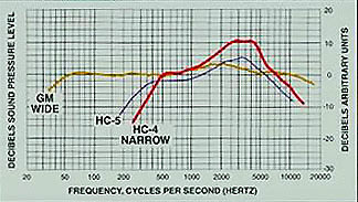
The Heil HC-4 and HC-5 elements,
and the Heil PR-781 microphone, are
excellent examples of transducers specifically designed for the transmission of
human speech with optimum articulation. The frequency response of the HC-5 is
300 Hz to 6 kHz at -6 dB, with 6 dB rise at 2 kHz. The HC-4 frequency response
is 600 Hz to 6 kHz at -6 dB, with 10 dB rise at 2 kHz. It will be seen that both
these elements are peaky around 2 kHz. This is, in effect, a form of pre-emphasis
which if accompanied by a judicious amount of compression, can increase
intelligibility at the distant station even under unfavourable band conditions.
Their output is significantly lower than that of an electret element, but will
drive the Pro-series radios to full output with Mic Gain at 50%, and about
6 dB
of compression. Refer to "DSP
Audio Settings for Heil Microphones".
The secret of effective, articulate SSB voice communications
lies in a combination of a -6 dB transmit audio response of 350 ~ 2700 Hz, 6 dB
of compression and 6 to 10 dB of pre-emphasis at 2 kHz in the microphone. That
said, a lower cutoff frequency in the 150 - 200 Hz range can yield improved
articulation under some propagation conditions. The operator should feel free to
experiment with different settings, but care should be taken to ensure a flat
transmitted audio response. The spectrum scope can be used to advantage here
(Scope on TX ON).
I have found that the following settings on the
IC-756Pro3, IC-756Pro2 and IC-756Pro work well with the Heil elements. These settings are
also applicable to the IC-746Pro/IC-7400, IC-7600, IC-7700 and IC-7800. Note that the
TBW settings are individually programmable only on the
IC-7600, the IC-7700, the IC-7800, the IC-756Pro3 and the IC-7000. (The IC-7000
does not have an EQ menu.) The settings in Table 5 are suggested as a starting
point, and can be further refined to suit individual voice characteristics. (The
microphone is plugged into the front-panel MIC socket.)
Table 5: IC-756Pro3 Settings for Heil Elements
| Heil Element |
Mic Gain |
TBW |
COMP*
|
Bass EQ dB |
Treble EQ dB |
| HC-5 |
12 o'clock |
MID |
12 o'clock |
-2 |
+3 |
| HC-4 |
1 o'clock |
NAR |
1 o'clock |
-2 |
+5 |
| Wide Range |
10 o'clock |
WIDE |
9 o'clock |
-3 |
+5 |
| PR-781 |
10 o'clock |
WIDE |
9 o'clock |
+1 |
+3 |
| PR-781 "DX" |
10 o'clock |
MID |
11 o'clock |
-1 |
+3 |
| Electret |
9 o'clock |
MID |
9 o'clock |
-3 |
+3 |
| *Set COMP
for 6 dB compression
on voice peaks (on bar-graph meter). |
The IC-756Pro3 transmitter offers a combination of
bass/treble equalisation and AF response adjustment (selectable low and high -6
dB points.) With this much flexibility, it should be possible to configure
the radio to work well with almost any microphone. Given the communications
mission referred to above, though, the best choice will always be a microphone
optimised for radiotelephone communications, as opposed to a microphone more
suited to broadcast or recording applications.
Output Transducers (Headphones and Speakers)
The same general considerations apply to output transducers as to microphones.
The amplitude/frequency response of a headset or speaker intended for radio
communications should closely match that of the receiver to which it is
connected. If the receiver is 6 dB down at 200 Hz and 2.7 kHz, the transducer's
-6 dB points should be in the same range. The use of a "wide-range" transducer
with a -6 dB response of 50 Hz - 18 kHz can actually be counter-productive, as
it can pass mains hum at the low end and white noise (hiss) at the high end.
These unwanted sounds can actually degrade articulation when listening to weak
and/or noisy signals.
Headphone Level
In the IC-756Pro3, there are 180Ω resistors in series with the tip & ring leads
of the front-panel [PHONES] jack (one resistor in each lead). (More information
here).
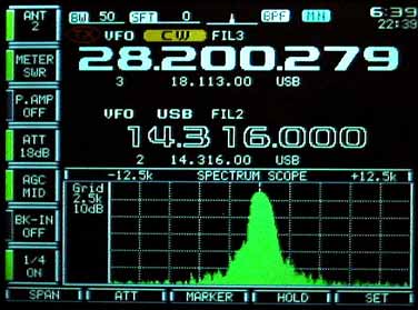
Spectrum Scope Vertical Sensitivity (August 2005)
With Preamp 2 enabled, 0 dB attenuation (RF and scope) and autotuner
disengaged , the Pro III spectrum scope will display a visible spike with 0.06 µV
(-131 dBm) at the antenna socket. (This was measured at 14.1 MHz with the
HP8640B signal generator, calibrated against the R&S URV4-03 RF
power meter with 0 dB probe.) The radio was also in CW mode, with the 500 Hz filter selected.
The corresponding figure for the Pro II
was 0.12 µV
(-125 dBm).
The Pro III scope, like its predecessors, has a
resolution bandwidth (RBW) of 1 kHz at -6 dB. View
a typical scope screen.
I have noticed a slight interaction between Spectrum Scope vertical amplitude
and Dual Watch BAL control setting on the IC-756Pro3.
Dual Watch was enabled, with 14316 kHz on MAIN, and 14186 kHz on SUB.
When I rotated the BAL control fully clockwise to cut off the Main channel, I
observed that the scope grass level rose approx. 6 dB.
Per the block diagram, the scope pickoff point is at the output of the MAIN (A)
1st mixer, which also feeds the MAIN Balance PIN attenuator. I believe that
the following is occurring: When the PIN attenuator is completely cut off, it
breaks the signal path to the next stage (the IF preamplifier feeding the 1st IF
combiner). This partially unterminates the MAIN 1st mixer output, causing the RF voltage at that point (and consequently at the input to the scope RF
amplifier) to rise by about 6 dB. There is no other apparent change in receiver
behaviour (e.g. instability etc.)
Comparing the 756Pro3 to the 756Pro and 756Pro2 yielded these results:
Pro - scope falls with BAL at 100%
Pro2 - no effect (scope fell 3 dB with BAL at 100% in one sample)
Pro3 - scope rises 6 dB with BAL at 100%
-
Note: Several units of each model type were
checked.
This is what I believe is happening: The Pro 1st mixer is followed by an LPF. When
the PIN diode attenuator is cut off, the LPF is mis-terminated (looks into an
open.) This apparently reflects a lower impedance back towards the 1st mixer,
loading it down and reducing the signal amplitude at the scope input.
In the Pro2, there is no LPF following the 1st mixer. The mixer output is fairly
low-Z, so the mis-termination when the PIN diode attenuator is cut off will not
cause much change in signal level at the scope pickoff point.
In the Pro3, the 1st mixer has a lower IF output than in the Pro or Pro2 (hence the need for an
RF amplifier in
the Pro3 scope input line). It is likely that the 1st mixer output is noise-matched to the PIN
attenuator, in which case it will have a higher source impedance to match the
load conjugately. The rise in load impedance when the attenuator goes to cut-off
will cause approx. 6 dB increase in output voltage. The scope input voltage will
rise by the same amount.
This is surmise on my part; I have not opened up the radio to take measurements.
This phenomenon is interesting, but not a major issue as it does not affect
receiver performance at all. In practice, with Dual Watch on, the BAL control is
normally set between 40 and 60%, and the interaction does not occur.
Comment on the IC-756Pro3 Autotuner (December 2005)
Matt KK5DR has found that the IC-756Pro3 autotuner tunes a little
faster than that of the IC-756Pro2. A quick check on my Pro3 confirmed
this.
There has been no change from the IC-756Pro2 in this area. Please refer to the
following links:
|
Q: Does
the IC-756Pro3 have a synchronous AM detector?
A: None
of the Icom DSP-based HF transceivers has an AM synchronous detector in
the sense of a phase-lock demodulator which regenerates the incident
carrier, demodulates the sidebands against the local carrier and "votes"
the sideband with the best S/N ratio.
All the Icom DSP-based radios (including the IC-746Pro, the IC-7800, the
IC-756Pro series and the IC-7000) employ the same DSP algorithm. This
models a phasing-type modulator and demodulator for SSB and AM. The
difference between SSB and AM is that in SSB, the unwanted sideband is
cancelled, whereas in AM the upper and lower sidebands are added in
phase to produce the composite baseband.
Unlike a true synchronous detector, the AM demodulation process in the
Icom DSP design does not "vote" the sideband with the best S/N ratio.
AM broadcast reception is very effective on the IC-756Pro series, but is
subject to selective fading. One can use ECSS (by receiving AM in SSB
mode) to reduce this, and select the quieter sideband manually.
Q: Can you explain the amplitude-sensitive
digital artefacts which appear on the transmitted AM signal?
A: With any system involving A/D and D/A conversion, quantizing
distortion will occur at high signal levels. This will manifest itself
as noise on modulation peaks. As the ADC and DAC used in the Icom radios
are 24-bit devices originally intended for high-grade audio
applications, quantizing distortion will be insignificant as long as the
devices are not overdriven.
Note that as the analogue input level to the ADC approaches the
"all 1's" point, quantizing distortion will increase sharply. If [MIC
GAIN] is set for 90% modulation, using the Spectrum Scope as
described here, the ADC will remain well within its linear range.
Also as discussed above, Po must not exceed 25W resting
carrier.
The spectrum-analysis test (described
here) yielded a clean display,
without visible artefacts.
In January 2007, I ran an AM listening test on my IC-756Pro3 at 25W resting
carrier and 90% modulation, using a simple tuneable demodulator
consisting of a military ME-61/GRC field-strength meter connected
to a good-quality headset . The recovered audio sounded smooth and
clean, without audible artefacts. This tended to confirm the
spectrum-analysis test. |
The RX-ANT input socket is intended for the connection of a separate receiving
antenna such as a Beverage, loop or long-wire. Such antennas, if co-sited with
the transmitting antenna, can induce extremely high voltages at the RX-ANT input
during transmission. This is particularly true on 160m and 80m. Recently, damage
to the front end of an IC-756Pro2 fed from a Beverage was reported on some
forums.
On researching this topic a little further, I noted that the 756Pro and 756Pro2
RF Unit boards have a varistor (R111) to absorb excess RF voltage, and a fuse
bulb (DS111) in the RF signal path from the RX-ANT jack to the ANT/ANT-R
selection relay (RL101). Excessive RF power applied to the RX-ANT jack will blow
DS111.
On the 756Pro3 RF-B Unit board, varistor R101 is still seen, but DS111 has been omitted.
Interestingly enough, though, the 756Pro3 RX-ANT circuit incorporates an RF
sensor (D101, Q103, Q104) which operates the selection relay (RL-101) when RF is
applied to the RX-ANT socket, thereby breaking the RX-ANT signal path. This
feature is lacking in the 756Pro2.
View partial schematics of the IC-756Pro3,
IC-756Pro2 and IC-7800 RX-ANT input circuits.
It is strongly recommended that an external protective relay circuit such as the
KD9SV Front End Saver be
connected between the receive antenna feedline and the RX-ANT input.
Q: Are the ANT1 and ANT2 inputs both grounded when power is off?
A: No, this is not the case. If we follow the RF signal path on the CTRL-A Unit
from ANT1 and ANT2 to the RFRX input (RF-B Unit), we see that when RL1, RL2, RL3
and RL4 are released, the signal from ANT1 is routed via RL3/1 NC, RL2 NC, RL1
NC, RL4 NC. L27 and L28 to J2 (RFRX). ANT2 is earthed to chassis via RL3/2 NC.
(IC-756Pro3 Service Manual, p. 10-5).
All relays are released when power is off.
View partial schematic.
Q. When I turn on the Calibration Marker, the S-meter reads S9 + 14dB with the
antenna disconnected and S9 +
11dB with the 40m antenna connected. Does this 3 dB difference mean that half
the Marker power is going out the
antenna?
Also, can I use the Marker to check S-meter calibration?
A. The marker amplitude as displayed on the spectrum scope will vary slightly
between individual radios. One
can use it as a rough check to see if the S-meter is reading correctly.
The marker signal is applied at the input of the splitter which feeds the
incoming RF signal to the Main and Sub
1st mixers. The load
impedance presented to the marker
source changes slightly if the antenna is connected with no preamp in the signal
path; this may account for the
drop in amplitude with the antenna connected.
With Preamp 1 or 2 selected, there is no change, as the preamp buffers the
marker injection point from the
antenna input.
I measured the marker signal leakage from the antenna socket with a Millivac
MV-723B broadband RF millivoltmeter terminated in 50Ω. The leakage is
negligible with either preamp in-line. With preamp off, marker on
and f = 7.4 MHz, I read -48 dBm at ANT2. The readings at 3.0 and 30.0 MHz were
both -52 dBm. This is the composite signal power of all the 100 kHz harmonic spikes
passing through the BPF for the selected frequency range. (Note:
The test frequency was just outside the 40m amateur band, to prevent damage to
the meter's sensor in the event of accidental keying.)
If you are concerned about this leakage, you can enable Preamp 1 or 2 whilst the
marker is on.
In response to an enquiry, I measured CW rise-times on my IC-756Pro3 using a
Tektronix 455 oscilloscope connected to a line sampler placed between the ANT2
socket and a 50Ω termination.
Test Conditions: f = 14050
kHz. Po = 10W. Time-base set to 1 mS/div.
Note:
Rise-time is defined as the time to go from zero to 100% Po.
6 vertical
divisions = 100% Po
(p-p).
The test results are listed in Table 6. The test screenshots can be seen
here.
Table 6: Rise Time
| CW Rise Time mS |
| Nominal |
Measured |
| 2 |
1.5 |
| 4 |
3 |
| 6 |
5 |
| 8 |
6 |
The rear-panel XVERT RCA jack is bidirectional. In response to a reflector request, I measured the transverter RF
drive level
(in transmit) on my IC-756Pro III. Here are the data:
Test Setup: IC-756Pro III, S/N 32025XX, with XVERT jack
connected via coax jumper to 50Ω terminated probe of Millivac MV-723B RF Millivoltmeter.
(IC-756Pro III User Manual, p. 18).
7-pin DIN plug with Pins 6 (XVRT) and 7 (+12V) bridged via 27KΩ 0.25W resistor,
plugged into Pro III ACC (2) socket to activate XVERT mode.
Pro III set to 28100.000 kHz, RTTY mode.
Table 7: Transverter drive levels, key down
| RF Power Setting |
XVERT Output, dBm |
| Minimum |
-21.0 |
| 50% |
-8.8 |
| Maximum |
-2.0 |
In receive, the signal applied to the XVERT jack is routed to
the RF BPF input. The transverter IF output power at this point should not
exceed approx. -13 dBm.
The ALC RCA jack is active in XVERT mode. A transverter equipped with
a negative-going ALC line (0 to -4V DC output) will be compatible with the
exciter's ALC jack.
There have been reports of low SSB power output in the IC-756Pro3. It has
been found that all too often, these are the result of incorrect measurement
methods, inaccurate test equipment and/or low DC primary supply voltage.
|
The following RF output test procedure should yield reliable results:
-
Measure the power output in CW, FM or RTTY mode with RF Power fully
clockwise, and your power meter terminated in a good-quality 50-ohm resistive
load. A calibrated Bird 43 or equivalent average-reading meter accurate to within 5% is
recommended.
-
Using an accurate DVM, check the primary DC voltage at the rear-panel power
socket with the radio delivering maximum output. At 13.8V DC, the transmitter
should deliver 100W or more to the load.
-
Run the SSB PEP test described
here. An
oscilloscope is required for this test.
-
If the displayed envelope amplitude on voice peaks is equal to the carrier
amplitude in RTTY mode for 100W output, the Pro3 PEP output is 100W.
-
Note: If the CW output measured in Step 1 is
significantly less than 100W with 13.8V primary DC input, or if PEP output
measured in Step 3 is significantly below 100W, the radio may require
realignment or repair. If the radio is still under warranty, or if you do not
have access to the test equipment specified in the service manual,
do not
attempt any alignment procedures. The radio should be sent in to an authorised
Icom service centre.
|
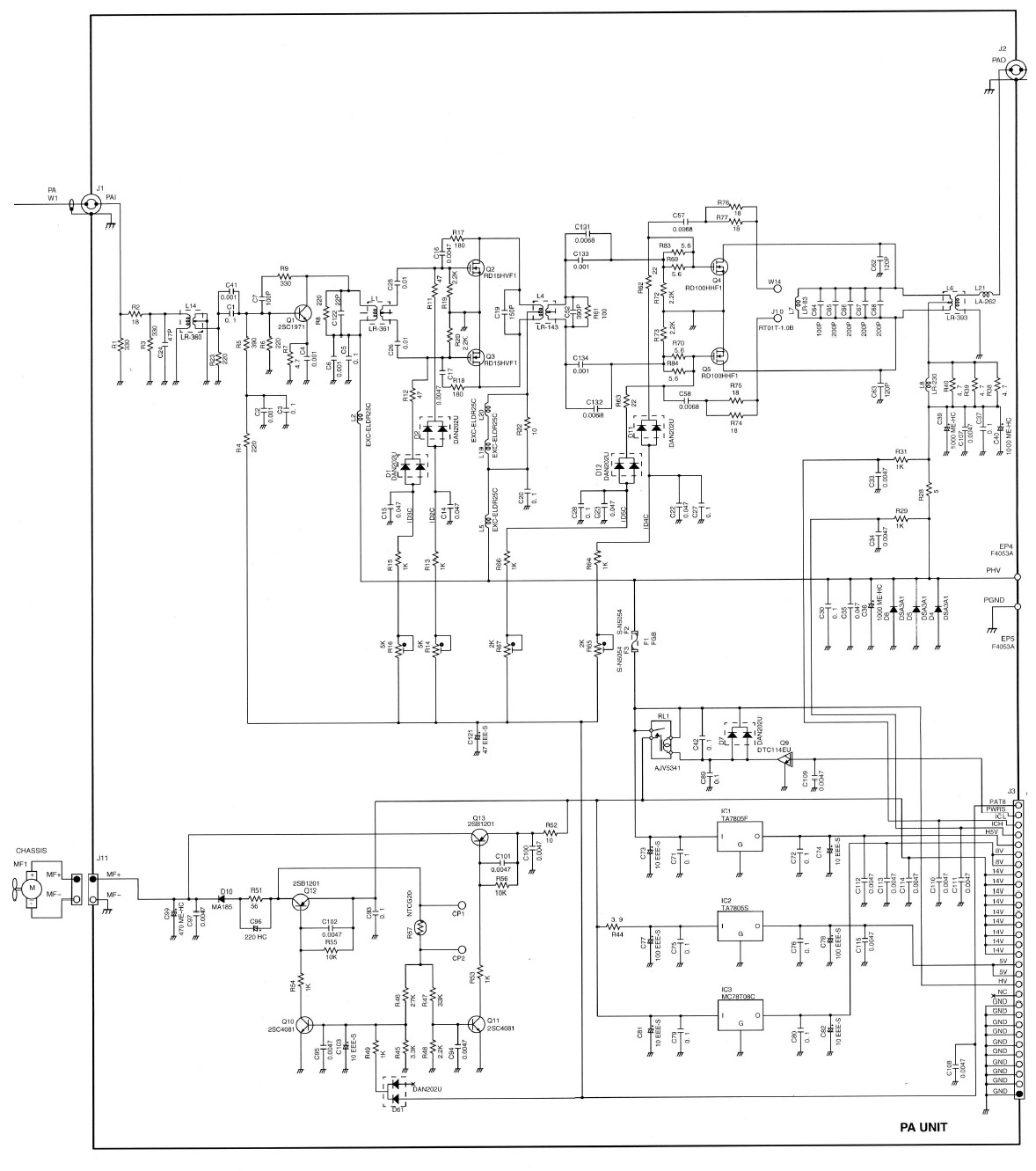
Mitsubishi, the manufacturer of the 2SC5125 used in the 756Pro series PA Unit,
have recently discontinued all their RF power BJT lines. This event has forced
Icom to design a new PA Unit based on MOSFETs. To the best of my knowledge, the new PA is showing up in
US/Canada Pro3's (#32 variant)* with S/N 32045XX and higher. The MOSFETs are also Mitsubishi parts.
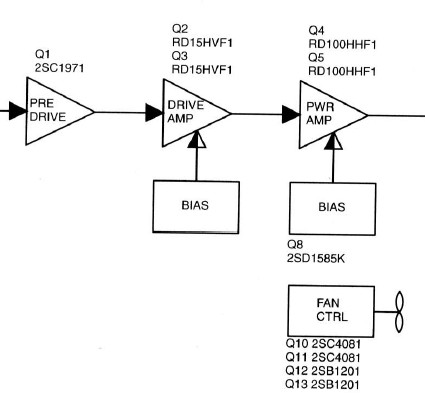
The original PA Unit uses BJT's, not FET's (2SC1971 pre-driver, 2 X 2SC1972
driver, 2 X 2SC5125 PA.) The line-up in the new PA Unit is as follows: 2SC1971 (BJT)
pre-driver, 2 X RD15HFV1 (MOSFET) driver, 2 X RD100HHF (MOSFET) PA. The HF/6m PA
in the IC-7000 also uses a pair of RD100HHF's.
A typical MOSFET circuit will have 13 dB power gain vs. 10 dB for a BJT circuit.
This reduces the required drive power by 50%, i.e. 5W vs.10W drive for
100W output. This will reduce the driver stage's IMD contribution. The MOSFET PA
already has slightly lower IMD (perhaps 1 or 2 dB), so the transmitter will be
cleaner overall.
Owners of IC-756Pro3's with the earlier PA Unit need not be overly concerned.
The 2SC5125 is a very tough device, and should last for many years with
reasonable care. The Toshiba 2SC2782 is a sub for the 2SC5125, and is available from
RF Parts singly and in matched pairs.
Furthermore, I am confident that Icom laid on an adequate stock
of BJT parts at their service centres to maintain the existing installed base when Mitsubishi advised
them of the impending discontinuance.
It should be noted that the IC-706 MkIIG went through a similar exercise a few
years ago when Motorola discontinued the PA devices.
Greg Buhyoff K2UM kindly provided a partial block diagram and
schematic of the new
PA Unit (originals courtesy Icom Inc.) I am also indebted to Greg for
supplying photos of the new PA Unit.
* Other regional variants will have different
serial number ranges for the change-over to a MOSFET PA.
Note: Rumours that Icom redesigned the PA
Unit in response to "PA failures" or "low output" are
patently untrue.
Q: On my IC-756 Pro III, I am trying to
understand how to get rid of that awful crackling and popping sound I hear when
on CW mode. This is the only mode on which I hear it; it is really distinct and
repeatable when I rotate the CW pitch control, and is most prevalent on 30 and
40 metres.
A: Here are some items to
check:
Filter settings: 250Hz "BPF" filter via menu or a "non-BPF"
500Hz filter set up via Twin PBT? (Less ringing for "non-BPF".)
CW shape factor (in Others/DSP menu): Sharp or Soft? (Less ringing with
"Soft".)
NB settings: How much NB is needed? Is NB threshold too high (> 75%), causing
distortion?
Antennas in use: Beverage on RX-ANT input or TX/RX antenna? If a Beverage
antenna is in use, there could be induced voltages on the antenna requiring
bleed-off.
AGC: Does the crackling and popping exist with the AGC turned off? If yes,
turn off pre-amps and attenuate the signal.
- In general, it is wise to avoid turning the AGC off, to prevent ADC
over-ranging which will cause severe distortion.
On 40m and below, the "dBm from
Heaven" technique is effective in reducing the noise level.
Test without antenna: Does the static and popping occur without an antenna?
If so, it is internally generated, and could indicate a faulty DSP Unit.
Comments by Matt, KK5DR.
It has been observed that the screen-saver never appears if a mono plug is
inserted in the front-panel ELEC-KEY jack.
This is normal. The ELEC-KEY jack has tip and ring leads. Even if
Keyer Type is set to
Straight in the KEYER menu,
the radio's CPU still senses both leads. Although a ground on the ring lead will
not key the transmitter, it still acts as an external event or "stimulus" which will clear the
screen saver.
If a mono plug is inserted, the plug shell will ground the ring lead, thus
clearing the screen saver. For this reason, a stereo plug should always be
plugged into the ELEC-KEY jack - even when using a straight key or
external keyer. The rear-panel KEY jack will accept a stereo or mono plug.
Every few months, a discussion of "IC-756Pro3 heat issues" pops up on the
forums. In fact, there is nothing to be concerned about. The
Pro3 does not overheat - as long as it is installed with adequate clear space
around it to allow sufficient air-flow for cooling.
At least
4" (10cm) of clear space around the top case cover and the rear panel are
recommended. The front feet should also be extended. The vent slots in the case
and rear panel must be unobstructed at all times.
If the Pro3 is correctly installed to allow sufficient air-flow, no additional
external fans should be necessary. This has been my experience with the entire
IC-756 series since 1998. To my knowledge, there have been no reported instances
of Pro3 failures due to overheating.
- It should be noted that direct attachment of small muffin fans to the case vent slots of
the Pro3 can be counter-productive. Should these fans fail for any reason,
they will obstruct the radio's air-flow with resultant overheating.
Read the caution on page ii of the Pro3 User Manual:
|
 NEVER install the transceiver in a place without adequate ventilation. Heat
dissipation may be affected, and the transceiver may be damaged. NEVER install the transceiver in a place without adequate ventilation. Heat
dissipation may be affected, and the transceiver may be damaged.
|
Refer also to Matt KK5DR's "Hot Radio"
page, and to the description of the Pro3's
temperature-control circuit.
-
"IC-756Pro
II Technical Report", Icom Inc., 2003. (PDF)
mirror
site
-
ARRL IC-756Pro3 Product Review (QST, March 2005 -
members only)
-
IC-756Pro III Service Manual
Links
Copyright © 2005-2009 A. Farson VA7OJ/AB4OJ. All rights reserved.
(Copyright in contributed items reposes with the respective contributors.)
Last revised: June 16, 2018