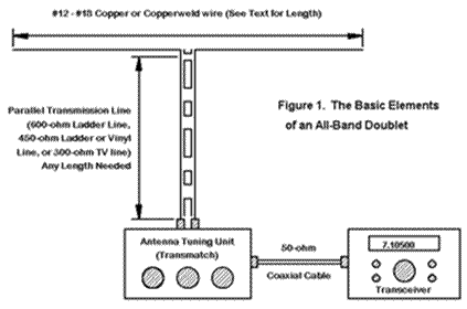
The Basic Doublet Antenna System
Too many new hams embarking on their first HF adventures think only of resonant dipoles fed with coaxial cable and plugged directly into the transceiver's output connector. Many end up with a mass of wires in the back yard as they try to make separate antennas for 80, 40, 15, and 10 meters. Others think that they are restricted to only one band because they have room for only one antenna. Too few modern Elmers have the personal experience to guide new HFers into one of the oldest ham antennas of all: the all-band doublet. 
Three popular lengths for the antenna
a. 130-140' (best, if you have the room and want the strongest results on 80 meters
b. 90-110' (works second best on 80 meters, with good results on all other bands).
c. 65-75' (good for 40 meters through 10 meters, but not for 80).
Notice that the precise length is not critical. Much more critical is getting the doublet as high as you possibly can. Although the antenna will work at low heights in the 20-25' range, it does much better (especially on 80 and 40) when it is higher than 35' up. You can use available trees for support
Of course, the ends of the wire need to be insulated from the support, so you will need end insulators and rope for the job. A good 1/4" sun (UV)-resistant synthetic fiber rope will hold up most antennas unless they are stressed too tightly.
Suppose that the antenna will not quite fit the space available. One standard technique of reducing the real estate needed is to set up the doublet in the inverted-Vee configuration. This version of the doublet tends to circularize the pattern, but reduce overall gain of the antenna at almost every frequency of use.
Consider bending the elements instead (if supports are available). Drooping ends are the most common version of this arrangement. However, setting up the antenna as a "Z," with all parts of the antenna wire as high as possible, often provides better performance. Drooping ends, and even ends bent in the same direction, provides some radiation cancellation, especially on the lowest bands of use, while the zig-zag version--if not too radically Z-ed--tends only to bend the pattern's directions
The Feedline:
The second element is the feedline. For this antenna, we use a parallel transmission line because it has very low losses, no matter what the SWR (within reasonable limits). 300-Ohm TV ribbon line will work, but it is not the strongest. Most ham dealers can get 400-Ohm or 450-Ohm vinyl-coated transmission line with larger wires. Completely open ladder line, with only insulated spaces, also works well but is less common.
Unlike coaxial cable, which you may run close to any object, parallel transmission line should be as free and clear of objects as possible. If the line must be brought down parallel to an object, such as the wall of a house, use insulated spacers to keep the line several inches away from the object. Avoid bringing the line near metal gutters and down spouts, power lines, conduits, or other metallic objects. Close proximity to metal can disrupt the balance between the wires of the feedline, adversely affecting its performance. Wherever the line must change directions, keep the angles shallow and, if at all possible, keep the line at right angles to the antenna wire.
Use special care when attaching the feedline to each side of the antenna wire center feedpoint insulator. Be sure that connections are mechanically secure, and then solder the feedline wires to the antenna wires. Test the connections for movable wire bends that may cause a break while swaying in the wind. Recently, some ladder-line "grabber" center fixtures have appeared on the market to secure the ladder line to the antenna wire and reduce the danger of breakage: they are well worth the investment.
One special problem deserves special attention: getting parallel feedline into the shack and over to the antenna tuner. There are almost as many ways to solve this problem as there are all-band doublet installations. The type of solution used depends largely on where the feedline enters the house.
If the feedline enters at a window, one can bring it through the window frame or through a board installed at the base of the window. Both have advantages and disadvantages. Bringing the line though the wooden window frame defaces the frame. Using a board on which the bottom section of the window closes requires special means to ensure insulation and security around the window. In each case, one can use a pair of bolts spaced about the same distance apart as the wires and make separate indoor and outdoor attachments. This feature is important, since it permits detachment of the feedline when electrical storms are imminent or when going on vacation.
Feeding a parallel transmission line through a wall calls for even greater care. One simple system (among many) uses a short length of PVC run through the wall and weather sealed around the edges. Some hams center the transmission line in the tube and hold it in place with fiberglass insulation. Others use plastic spacers with a center cutout to hold the line in place and seal the tube. There are many variations on this theme, but the old idea of simply slamming a window frame down on the transmission line at the window should be discouraged, especially with metal window frames. In all cases, there should be a way of disconnecting the transmission line out of doors and grounding it.

The Antenna Tuning Unit or Transmatch
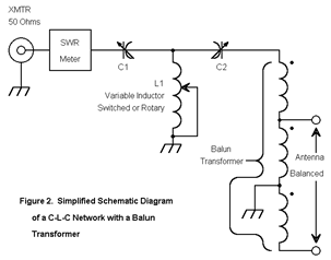
The "antenna tuner" is a network for transforming the impedance that is present at the shack end of the transmission line to another value, normally 50 ohms. An all- band doublet shows a different feedpoint impedance at each frequency of operation. The exact length of the antenna relative to the frequency will largely determine that impedance. The feedline will transform that impedance continuously along its length, repeating values every half wavelength of line. Since most transmission lines have a velocity factor, a half wavelength of line will be shorter than a true half- wavelength for the frequency of interest.
All of this together means that the exact impedance presented to the antenna tuner will vary from band to band and from one antenna installation to another
Some source content on this page from W4RNL: If you need anymore information on antenna's of this type this web page makes great reading to get you up and running on building your antennas. L. B. Cebik, W4RNL