Spectrum Lab is designed for real-time analysis of audio data. But you can also process data saved in wave files (and others), and you can save the in- or output signal in a wave-audio file without interrupting the analysis.
See also:
While audio streams are processed by SL in real time, they can be saved as a wave file (for "logging", "archiving" etc).
You can tap the recorder to any node in SL's circuit window, for example L1/R1 = input, L5/R5 = output, or (for the EbNaut recorder) to the decimated input for the main frequency analyser's FFT . For most applications you will save the input as a wave file to have all opportunities for later post-processing (except, maybe, when only a small portion of the frequency range is of interest and the file size shall be kept low.. more on that later).
You don't necessarily have to save the wave file data with the same sample rate as the ADC. Instead, you can use the lowest possible sample rate for the wave file to save a lot of disk space... consider this: A software VLF radio uses an ADC running at 44.1ksamples/second, and converts the signal down to 650 Hz, filtered to a bandwidth of 100Hz. Practically, it would be enough here to save the "downconverted" signal with 5512 samples/second which occupies only 12.5 % of the disk space. (5512 is the lowest "standard" sample rate supported by most soundcards, but don't bet on that)
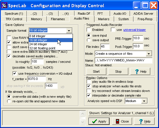
The settings for wave file logging can be modified in the configuration dialog, which can be opened through the main menu (Options .. Wave file settings) :
To start or stop logging, use either the file menu (File..Audio Files and Streams..
'Save input as audio file' or 'Save output as audio file'), or one of Spectrum
Lab's interpreter commands.
In the save dialog (which can be opened with a double click into the 'name' field),
you can manually enter a template instead of a normal filename, for example:
C:\vlf\<YYYYMMDD_hhmm>.wav
The string between angle brackets will be replaced by the current date and time when actually
creating the file, as explained for the 'stream log'
(in fact, such name templates can be used for the audio recorder, and in a few other places too).
When creating a file on January 16, 2015 at 19:30 UTC,
the example shown above would create a file named
C:\vlf\20150116_1930.wav .
This feature saves a few seconds (time not wasted in a stupid fileselector box) when in a hurry to record a new file.
The same applies to the triggered audio recorder, which in fact uses the same
filename (or its template) as described above for normal audio logging.
While saving the audio stream in a wave file, the
progress button will tell you how
many kBytes are already written to the file. Be careful
not to run out of disk space while logging, because Windows may crash in
that case. If this is an issue, use a different partition of even a different
harddisk to record wave files.
If a GPS is connected (and configured), there may be an auxiliary file (*.aux) written along with each audio file (*.wav). The auxiliary file will contain GPS coordinates, timestamps, and possibly some other data. If you don't need the AUX files, set the GPS output interval to zero in the GPS configuration window. Except for the file extension, aux files have the same names as their corresponding wave audio files. Without auxiliary files, there will only be one single GPS position in an extra chunk ("inf1") of the wave file header. More details about logging (exporting) GPS data along with audio files can be found in an extra document (gps_decoder.htm).
(*) In the author's opinion, a kByte ("kilobyte") still consists of 1024 bytes. Don't urge me to call this a "kibibyte" from now on, just because some egghead discovered that 1024 is not equal to 1000. A "kilobyte" has never been 1000 bytes. Full stop. :o)
As an alternative to the "normal" logging of wave files as explained in the previous chapter, the recording of audio files can also be started automatically (without using the FILE menu, and without the help of the interpreter). For example, you want to record the raw input only if "something interesting" happens (for example, the call of a bat in a certain frequency range). You may also want to record a few seconds before the event actually happened, and a only few seconds after that (to avoid filling the disk with useless data).
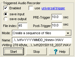
To configure the triggered recoder, select Options..Wave
File Settings in SpecLab's main menu, on the panel labelled
Triggered Audio Recorder (details in an extra
document, please follow the link).
To start or stop wave file analysis, use Spectrum Lab's main menu (under "File" ... "Audio Files & Streams" ).
Decide which of this file analysis modes you want to use by choosing the corresponding submenu. Then a file selector box opens in which you can select the audio file.
After selecting one or more wave-file to be analysed, a dialog window appears where some parameters of the wave file are displayed. Some parameters (like the sample rate) can be adjusted for the following analysis.
The sample rate in a file is often different from the sample rate of the soundcard. For ELF work, the wave files are often decimated to a low sample rate to save disk space. For this reason, you often need a different FFT size to analyse files than for real-time analysis with the soundcard. Before the above dialog opens, the program calculates the best FFT size to achieve a similar frequency resolution as for real-time analysis. The resulting resolution is shown in the audio file analysis dialog (see screenshot above). If you are not satisfied with the FFT settings, you can modify the settings before clicking "OK" to start the file analysis.
While the analysis runs, the progress button shows the current playing time, the file name, and some other info.
Note: The file analysis without playback runs much faster than the real-time analysis. You can select "slow","medium" and "fast" analysis in the dialog, or on the "Wave Files" tab in the configuration dialog. The different "speeds" have the following effects (in fast file analysis mode only !):
Note: The option 'plotting the result in fast file analysis mode' was implemented in October 2004. It didn't work in older versions !
When finishing Fast File Analysis, the program will not automatically switch back to real-time operation (analyse samples from the soundcard), because you may want to analyse other files too, and see the result in the same spectrogram and/or plot of analysed data. To return to real-time processing with the soundcard, use the main menu, "Start/Stop"..."Start Audio Thread".
Besides the uncompressed wave file format, the program supports the following file formats for input (analysis):
These raw, uncompressed, headerless data files - for example, the output of a 16-bit DAC dumped into a file without any format conversion.
To analyse these files, you will need to fill out some additional fields in the 'File Analysis' dialog which automatically pops up after selecting the file:
Explained in a separate file .
The recording and playback can be controlled by interpreter commands, for example through one of the programmable buttons in the left part of the main window. You can assign any function to a button, for example to start / stop a recording, or to temporarily pause replay / analysis.
A list of commands related with wave-audio file can be found in the file 'interpr.htm#wave_proc' . Here just an excerpt:
In addition, there's an extra set of commands for the Triggered Audio Recorder .
For certain applications (like the EbNaut wave recorder), it was necessary to embed some 'extra' information in wave files written by Spectrum Lab.
If this causes problems with other programs (which cannot skip such unknown chunks, like very old versions of Spectrum Lab..), you can turn off this feature in the configuration dialog .
The following 'extra' RIFF chunks may be written in wave audio files by Spectrum Lab, depending on the configuration :
If a GPS is connected (and configured), there may be an auxiliary file (*.aux) written along with each audio file (*.wav). The auxiliary file will contain GPS coordinates, timestamps, and possibly some other data. If you don't need the AUX files, turn off the option 'save extra data in auxiliary files' on the 'Wave Files' tab in SL's configuration screen:
To change the interval in which GPS data are emitted to the aux file, modify the GPS output interval in the GPS configuration panel (see right image below, default is 1 second) :
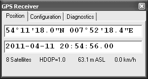
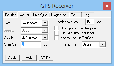
Except for the file extension, aux files have the same names as their corresponding wave audio files. Without auxiliary files, there will only be one single GPS position in an extra chunk ("inf1") of the wave file header.
All details about logging (exporting) GPS data along with audio files can
be found in an extra document
(gps_decoder.htm).
An example of an aux file with GPS- and additional data (added by
means of an interpreter command) is
here .