
IK2RND ICOM RAM Board Information
The information on this page is courtesy of Roberto Nardo, IK2RND. It is posted here for the benefit of amateurs in the US and other English countries that own and use ICOM amateur radio products with the EX-314 volatile RAM program board. For more information or to obtain the RAM board, contact Roberto at the e-mail address listed below.
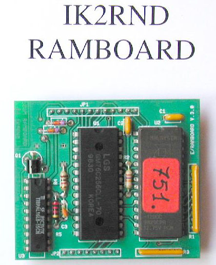
EPROM/RAMBOARD
by Roberto Nardo, IK2RND
For ICOM
IC-751/A IC-751 IC-745
ICR71E/A and IC-271 IC-471 IC-1271
The EPROM/RAMBOARD card directly replaces the ICOM RAM UNIT EX-314 and EX-314 # 01. No soldering is needed and the frequency coverage is extended from 10 KHz to 30.9 MHz (for HF Rigs) and for the IC-271 2 meter radio, the range is extended to 142.400-153.990 MHz.
The card contains an EPROM programmed with data related to the equipment's programming and lookup table, as well as a RAM to store 32 memory channels. The information in the RAM memory is maintained by a lithium battery that can last more than 7 years.
Here's a close-up comparison view of the original EX-314 and the replacement board.

INSTALLATION
First off, since you're replacing the memory board in the radio, write down any frequencies in the VFO A/B or any of the 32 memory channels you wish to reprogram into the new unit.
Before you begin the installation, unplug the line power cord and the antenna cable and place the equipment on a well lighted work table.
With the help of a well fitting screwdriver remove the Phillips (cross-head) screws that holds the upper cover and then remove the cover. IC-R71 and IC-745 owners must pay attention to the loudspeaker cable that is attached to the top cover. (The speaker for the IC-271, 471 and 1271 is attached to the bottom cover.)
Now remove the bottom cover. The original ICOM EX-314 board is plugged on the logic board mounted in the lower part of the radio. You can easily recognize it because it is equipped with an ICOM # (XX) Lithium battery.
The EX-314 is connected to the logic board by an 8 pin connector and a 12 pin connector secured with small Phillips (cross head) screws. Remove the screws, then carefully remove the board so as not to bend the pins.
Insert the new board, paying careful attention to the connectors and pin alignment. The logic board lacks guides or other mechanisms to ensure proper alignment, but with some patience and care, this step is easy to do.
Reinspect and verify that the installation is correctly seated onto the logic board, then power on the radio. Set it in the normal operating positions and verify the radio powers up. Power down the radio, then close up the radio by putting back the bottom and top covers and reinstalling the screws.
The general coverage range
of the HF rigs will be extended from 10 KHz as far as 30.9 MHz.
Nothing else has changed.
Good DX de IK2RND
or [email protected] on the Packet BBS
The EPROM/RAMBOARD battery has a life span of about 7 years. You will recognize the need to replace it when you run into problems storing data into your radio's memory. To replace battery you must remove the board from the radio and to do this you must switch off the equipment and unplug the line power cord.
Follow these instructions:
Write down any frequencies in the VFO A/B or any of the 32 memory channels you wish to reprogram into the new unit.
Unsolder the drained battery using a low power solder iron (40-50 W). Carefully solder new battery onto the board paying attention not to cause solder bridges and short circuits. Plug the RAM board into the radio.
Power on the rig. You will see anomalous indications on your display, such as "CW AM LSB USB RTTY" simultaneously displayed, unusual frequencies such as 666.667.8 MHz etc. This is due to the fact that the contents of the RAM data are absolutely random. Keep cool now!
The RAM data must be preset and initialized again after the you replaced the battery. Note that the RAM stores 32 channels of memory data and the last VFO A/B frequencies. Replacing the battery on the board has erased these data, but not the programming stored in the EPROM that is essential to initialing the radio.
Presetting IC-751 IC-751A IC-745
- Push the HAM/GEN button to switch the radio into the HAM mode. The red GENE (General Coverage) indicator be turned off.
- Push the BAND button. By rotating the tuning knob you will now see and verify that the 9 HF bands are being selected.
- Select an emission mode, such as CW, SSB, etc.
- Press the VFO/M and A/B buttons to select the VFO-A mode. Push the A=B button so that the VFO-B frequency will be now the same as VFO-A frequency.
- Then go on to set and store your preferred frequencies in the 32 memory channels.
- Push the LSB button. Only the LSB operation mode will be active.
- Key in a correct frequency using the numeric keypad. For example 7.050.0 MHz and save it in VFO-A.
- Push the VFO A=B button. The two VFOs will be now set to the same frequency. The equipment is preset and initialized.
- You may now program the 32 memory channels.
Presetting IC-271, IC-471, IC-1271
- To restore the normal operation of these equipments you need to connect up a restart push button switch (not provided) to the LOGIC BOARD using the cables supplied with the card. The wires and switch connect pin 2 of J3 to pin 2 of J5 on the LOGIC BOARD.
- You will need to push the following sequence:
- The restart button,
- FM mode key,
- Restart button again.
- The display will now show one of these frequencies: 144.000 MHz FM for the IC-271; 430.000 for the IC-471; 1240.100 for the IC-1271.
- Push VFO A=B to set both VFOs.
- You can now program the 32 memory channels. In the IC-271 the restart button allows you to broaden the band from 144-146 (IC-271E) and 144-148 (IC-271A) to 139-153 MHz.
- The board doesn't interfere with the mounting of the internal PS-35 power supply.
-
The price is $54 for the board, plus $11
 for delivery by air mail registered parcel.
Roberto accepts Paypay.
for delivery by air mail registered parcel.
Roberto accepts Paypay.
- Roberto's mailing address is:
Via Marchesi, 27
I 27100 Pavia
Italy
- Find out more about the RAM board and ordering information by contacting: [email protected]
RAM Board information Copyright © 2000 Roberto Nardo
Copyright © 2000-2015 Ron Hashiro
November 18, 2000. Updated: October 17, 2013 DISCLAIMER: Ron Hashiro Web Site is not responsible for the content at
any of the external sites that we link to and therefore
are not necessarily endorsed by us.