|
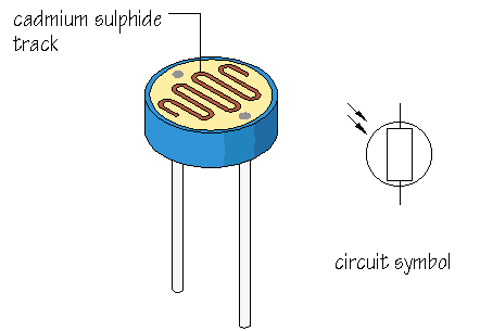
The light-sensitive part of the LDR is a wavy track of cadmium sulphide. Light energy
triggers the release of extra charge carriers in this material, so that its resistance
falls as the level of illumination increases.
A light sensor uses an LDR as part of a voltage divider.
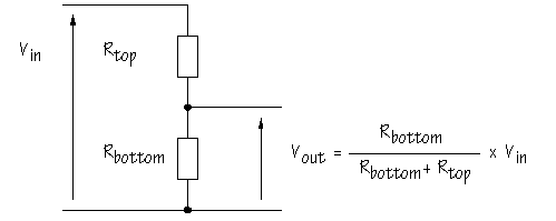
The essential circuit of a voltage divider, also called a potential divider,
is:

As you can see, two resistors are connected in series. with Vin ,
which is often the power supply voltage, connected above Rtop . The
output voltage Vout is the voltage across Rbottom
and is given by:
 |
It may help you to remember that Rbottom appears on the top line of
the formula because Vout is measured across Rbottom
.
| KEY FORMULA: |
This is an extremely useful formula which you should learn thoroughly |
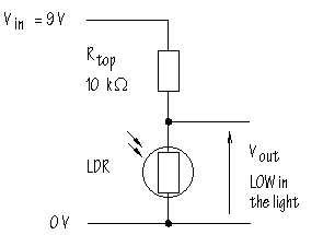
What happens if one of the resistors in the voltage divider is replaced by an LDR? In
the circuit below, Rtop is a 10  resistor, and an LDR is used as Rbottom : resistor, and an LDR is used as Rbottom :

Suppose the LDR has a resistance of 500  , 0.5 , 0.5  , in bright light, and
200 , in bright light, and
200  in the shade (these values are
reasonable). in the shade (these values are
reasonable).
When the LDR is in the light, Vout will be:

In the shade, Vout will be:

In other words, this circuit gives a LOW voltage when the LDR is in the light, and a
HIGH voltage when the LDR is in the shade. The voltage divider circuit gives an output voltage
which changes with illumination.
A sensor subsystem which functions like this could be thought of as a 'dark
sensor' and could be used to control lighting circuits which are switched on
automatically in the evening.
Perhaps this does not seem terribly exciting, but almost every sensor circuit you can
think of uses a voltage divider. There's just no other way to make sensor subsystems work.
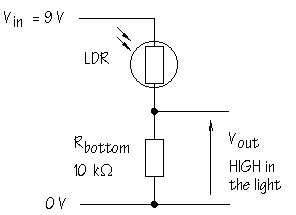
Here is the voltage divider built with the LDR in place of Rtop
:

What effect does this have on Vout ?
The action of the circuit is reversed. that is, Vout becomes HIGH
when the LDR is in the light, and LOW when the LDR is in the shade. Substitute the
appropriate values in the voltage divider formula to convince yourself that this is true.
More on Voltage Dividers >>>
|


