|
|
|
MODULE V - FUNDAMENTALS OF ELECTRONICS
In the topic current we learn that certain materials such as copper have many free electrons. Other materials have fewer free electrons and substances such as glass, rubber, mica have practically no free electron movement therefore making good insulators. Between the extremes of good conductors such as silver, copper and good insulators such as glass and rubber lay other conductors of reduced conducting ability, they "resist" the flow of electrons hence the term resistance. |
 |
|
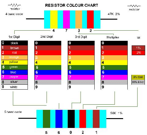
The five band code is more likely to be associated with the more precision 1% and 2% types. Your "garden variety" 5% general purpose types will be four band resistance codes. Free download Color Code Convertor Program. The specific resistance of a conductor is the number of ohms in a 1' (305mm) long 0.001" dia round wire of that material. Some examples on that basis are Silver = 9.75 ohms, Copper = 10.55 ohms, Nickel = 53.0 ohms and Nichrome = 660 ohms From this information we can deduce that for a voltage applied to a piece of Nichrome wire , only around 10.55 / 660 = 0.016 of the amount of current will flow as opposed to the the current flowing in the same size copper wire. The unit of resistance is the ohm and 1 ohm is considered the resistance of round copper wire, 0.001" diameter, 0.88" (22.35 mm) long at 32 deg F (0 deg C). RESISTANCE IN SERIES AND PARALLEL It follows if two such pieces of wire were connected end to end (in series) then the resistance would be doubled, on the other hand if they were placed side by side (in parallel) then the resistance would be halved! This is a most important lesson about resistance. Resistors in series add together as R1 + R2 + R3 + ..... While resistors in parallel reduce by 1 / (1 / R1 + 1 / R2 + 1 / R3 + .....) Consider three resistors of 10, 22, and 47 ohms respectively. Added in series we get 10 + 22 + 47 = 79 ohms. While in parallel we would get 1 / (1 / 10 + 1 / 22 + 1 / 47) = 5.997 ohms. RESISTANCE AND POWER Next we need to consider the power handling capability of our resistors. Resistors which are deliberately designed to handle and radiate large amounts of power are electric cooktops, ovens, radiators, electric jugs and toasters. These are all made to take advantage of power handling capabilities of certain materials. From our topic on ohms law we learnt that P = I * I * R that is, power equals the current squared times the resistance. Consider our example above of the three resistors in series providing a total resistance of 79 ohms. If these resistors were placed across a 24 volt power supply then the amount of current flowing, from ohms law, is I = E / R = 24 / 79 = 0.304 amperes. Using any of our power formulas we determine that 0.304 amperes flowing through our 79 ohm resistance dissipates a combined 7.3 watts of power! Worse, because our resistors are of unequal value the power distribution will be unequal with the greater dissipation in the largest resistor. It follows as a fundamental rule in using resistors in electronic circuits that the resistor must be able to comfortably handle the power it will dissipate. A rule of thumb is to use a wattage rating of at least twice the expected dissipation. Common resistors in use in electronics today come in power ratings of 0.25W, 0.5W, 1W and 5W. Other special types are available to order. Because of precision manufacturing processes it is possible to obtain resistors in the lower wattage ratings which are quite close in tolerance of their designated values. Typical of this type are the .25W range which exhibit a tolerance of plus / minus 2% of the value. Resistors come in a range of values but the two most common are the E12 and E24 series. The E12 series comes in twelve vaues for every decade. The E24 series comes in twent four vales per decade. E12 series - 10, 12, 15, 18, 22, 27, 33, 39, 47, 56, 68, 82 E24 series - 10, 11, 12, 13, 15, 16, 18, 20, 22, 24, 27, 30, 33, 36, 39, 43, 47, 51, 56, 62, 68, 72, 82, 91 You will notice with the E12 values that each succeeding value falls within the plus / minus 10% of the previous values. This stems from the real old days when resistances were stated as within 20% tolerance (accuracy). Later values of plus / minus 5% tolerance led to the E24 range of resistance. Quite common today are 2% tolerance metal films types but for general purpose use we tend to stick to E12 values of resistance in either 1%, 2% or 5% tolerance. Cost is the determining factor and many retailers now stock the 2% range of resistance as a standard to minimise stocking levels and also at reasonably low cost. As examples of say the "22" types (red - red) from the E12 series we get 0.22, 2.2, 22, 220, 2,200, 22,000, 220,000 and 2,200,000 or eight decades of resistors. RESISTANCE COLOUR CHART CODES Here in this large colour chart is the resistance colour code - learn the sequence forever - BLACK, BROWN, RED, ORANGE, YELLOW, GREEN, BLUE, PURPLE, SILVER, WHITE I have accomodated two current colour banding of resistances - four band and five band resistance colour code. It should be pretty self explanatory I hope.
|
|
|
|

Copyright �2000-2002 [email protected] -- All Rights Reserved -- Designed by WebCreations