|
|
|
MODULE V - FUNDAMENTALS OF ELECTRONICS
Temperature sensors
The resistance of most common types of thermistor decreases as the temperature rises. They are called negative temperature coefficient, or ntc, thermistors. Note the -t� next to the circuit symbol. A typical ntc thermistor is made using semiconductor metal oxide materials. (Semiconductors have resistance properties midway between those of conductors and insulators.) As the temperature rises, more charge carriers become available and the resistance falls. |
|
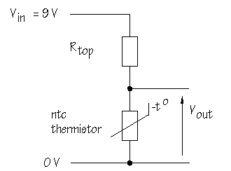
Although less often used, it is possible to manufacture positive temperature coefficient, or ptc, thermistors. These are made of different materials and show an increase in resistance with temperature. How could you make a sensor circuit for use in a fire alarm? You want a circuit which will deliver a HIGH voltage when hot conditions are detected. You need a voltage divider with the ntc thermistor in the Rtop position:
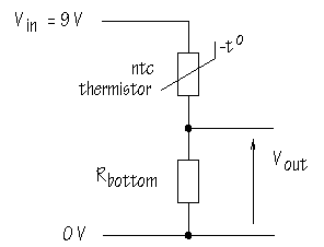
How could you make a sensor circuit to detect temperatures less than 4�C to warn motorists that there may be ice on the road? You want a circuit which will give a HIGH voltage in cold conditions. You need a voltage divider with the thermistor in place of Rbottom :
This last application raises an important question: How do you know what value of Vout you are going to get at 4�C? To answer this question, you need to estimate the resistance of the thermistor at 4�C. Lots of different types of thermistor are manufactured and each has its own characteristic pattern of resistance change with temperature. The diagram below shows the thermistor characteristic curve for one particular thermistor:
On the y-axis, resistance is plotted on a logarithmic scale. This is a way of
compressing the graph so that it is easier to see how the resistance changes. Between 100
As you can see, this thermistor has a resistance which varies from around 70
Where:
RT is the resistance at temperature T
in Kelvin (= �C +273) You don't need to think about applying this equation at the moment, but it is useful to know that the information provided in catalogues is sufficient to allow you to predict thermistor performance. Using a spreadsheet such as Excel, it is possible to to generate characteristic curves for any thermistor by calculating resistance values for a range of temperatures.
With RT0 =
20
From the graph, the resistance at 4�C can be estimated as just a little
less than 60
What this means is that selecting a value for Rtop close to 58.2 Sensor devices vary considerably in resistance and you can apply this rule to make sure that the voltage dividers you build will always be as sensitive as possible at the critical point. Thermistors turn up in more places than you might imagine. They are extensively used in cars, for example in:
Thermistors are used to measure surface and deepwater sea temperatures in helping to monitor El Ni�o ocean currents. Less obviously, thermistors are used to measure air flow, for instance in monitoring breathing in premature babies. |
|
|
|
Copyright �2000-2002 [email protected] -- All Rights Reserved -- Designed by WebCreations


