|
|
|
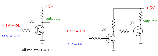
MODULE V - FUNDAMENTALS OF ELECTRONICS What are the digital basics? Digital circuits work on the basis of a transistor being used as a switch. Consider a light switch, a transistor can be considered almost the same and in some circuits transistors are used to control large amounts of power with very little input power being used. Look at figure 1 below. Here are two crude transistor switch circuits. In the first circuit if there is no voltage applied to the base of Q1 then it is not switched "on" and accordingly the + 5V passing through the 10K load resistor from our + 5V supply appears at both the collector of the transistor and also at output 1. If we apply + 5V to the base of Q1 then because it is greater than 0.7 V than the grounded emitter, see
the topic "transistors" for much greater detail on that operation, Q1 will switch on just like a light switch causing the + 5V from our supply to drop entirely across the 10K load resistor. This load could also be replaced by a small light bulb, relay or LED in conjunction with a resistor of suitable value. In any event the bulb or led would light or the relay would close.

Figure 1. - transistors as digital switches in digital basics |
|
The basic principle in digital basics is that we have just created an "electronic switch" where the positive voltage on the base produces zero voltage at the output and zero voltage on the input produces the + 5V on the output. The output is always the opposite to the input and in digital basics terms this is called an "inverter" a very important property. Now looking at Q2 and Q3 to the right of the schematic we simply have two inverters chained one after the other. Here if you think it through the final output 2 from Q3 will always follow the input given to Q2. This in digital basics is your basic transistor switch.
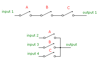
Depending upon how these "switches" and "inverters" are arranged in integrated circuits we are able to obtain "logic blocks" to perform various tasks. In figure 2 we look at some of the most basic logic blocks.

Figure 2. - digital switches in digital basics In the first set of switches A, B, and C they are arranged in "series" so that for the input to reach the output all the switches must be closed. This may be considered an "AND-GATE". In the second set of switches A, B, and C they are arranged in "parallel" so that for any input to reach the output any one of the switches may be closed. This may be considered an "OR-GATE". These are considered the basic building blocks in digital logic. If we added "inverters" to either of those blocks, called "gates", then we achieve a "NAND-GATE" and a "NOR-GATE" respectively.
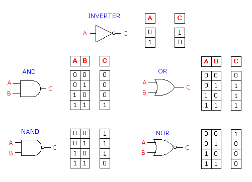
Here in figure 3 we examine the digital basics in schematic form.

Figure 3. - digital basics in schematic form Now here we have depicted four major logic blocks AND-GATE, NAND-GATE, OR-GATE and NOR-GATE plus the inverter. Firstly the "1's" and the "0's" or otherwise known as the "ones" and "zeros". A "1" is a HIGH voltage (usually the voltage supply) and the "0" is no voltage or ground potential. Other people prefer designating "H" and "L" for high and low instead of the "1's" and the "0's". Stick with which system you feel most comfortable. Several interesting points emerge here. Of interest to the next section on binary numbers is the pattern of all the inputs for each logic block. Not only are they identical but, for only two inputs A and B there are four possible output situations which are called "states". These are digital basics. There actually can be many numbers of inputs. An eight input NAND-GATE is a common and quite useful digital logic block. Next of particular interest is if you study them very carefully, that for the very identical inputs, each of these logic blocks gives us a totally different output result. Compare them. Finally for the same inputs the NOR-GATE outputs are the direct opposite to the AND-GATE outputs while the OR-GATE outputs are the direct opposite to the NAND-GATE outputs. |
|
|
|
Copyright �2000-2002 [email protected] -- All Rights Reserved -- Designed by WebCreations


