During experimental testing of ALCATEL XVRT modules for 5.7GHz and 10GHz was neccesary to design a new IF down converter to 144 or 432MHz, power supply and controller. The frequency conversion is required to reject the image frequency, 1st IF will be relative high 700...1600MHz. The idea was to be an universal solution for any ALCATEL XVRT 7/11GHz. Also other versions are supported but not suitable for ham radio.
The design must to meet next requirements:
- Flexible power supply, selectable +6V or +10V for driver stage due to different PA driver.
- Negative 5 volts bias voltage interlocked with +10V, +6V and +5V in order to avoid failure of FET transistors by over current in case of lost bias.
- PLL controller for 1st Alcatel LO ADF4106 and 2nd LO MAX2871. Jumper configuration 5.7/10GHz, high/low injection, 144 or 432 2nd IF, IF shift (+1MHz) to 145/433MHz in case of local QRM.
- Output power monitoring and internal temperature sensor.
- Coaxial relay sequencer.
- Fan controller according adjustable setpoint.
- Integrated RF VOX, PTT or DB6NT voltage over coaxial.
- Good quality PLL reference 10MHz OCXO.
- SAW filters use for best image rejection and no tuning.
- LCD 2x16 I2C
- And many other small details...
Note:
Several versions of IF Converter/PSU were tested (sequencer with transistors/uC integrated, LTC6946/MAX2871 2nd LO, LED bargraph/LCD power monitoring, HMC213/RMS-25MH mixer). In order to avoid any confusion between photos and text content, I will speak only about last design - version 3, but the PCB is updated to version 4 to fix some small mistakes.
PCB version 4 was not yet manufactured. Is 99% same with tested version 3 (shileding improvment of MAX2871, ADF4106 uC lock detection correction, internal/external power monitoring for PA use, silkscreen correction).
The schematic diagrams are matched with PCBs vers. 4.
Description of PSU/Controller Board:
The power supply has been designed to provide the necessary voltages for the Alcatel XVRT unit. The required 10V voltage for PA FET is interlocked with the negative bias voltage to avoid failure of the transistor in case of -5V malfunction.
Power supply voltage for PA driver stage can be selected 6V or 10V according XVRT type. Check the datasheet of driver power MMIC!
In general 11GHz version needs 6V and 7GHz with 10V. During experiments of 7GHz conversion to 5.7GHz was found better matching if power supply is decreased to 6V. Final PA stage is supplied only with 10V,regardless of model. Please note that above photo of PSU/Controller board v.3 has wrong silkscreen of driver voltage selection versus frequency. The error is fixed on layout v4. For more informations read 7GHz or 11GHz page.
The transverter is capable of operating even at 11V, suitable for portable use when the battery is discharged. OCXO supply has been stabilized at 10V...10.5V even if it is below of specifications. Frequency drift due to unstable battery voltage is avoided. Switching power supply provides 6V and although I tried to avoid it, it was not possible because the TX driver absorbs a current over 2A and the dissipated power is ~15W for a linear regulator.
Negative voltage is generated by MAX660, higher current DC/DC voltage converter. I didn't try to use ICL7660 due to ~25mA/-5V required by XVRT.
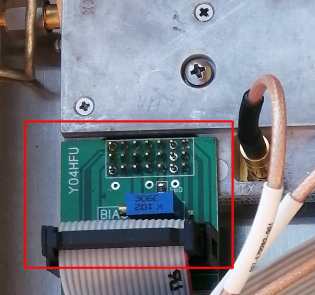
PA stage idle current can be checked across "TP Id" terminals. Remove the jumper and read the current by an ammeter. The current is adjusted according datasheet (class A). Bias adjustable resistor is located on "21 pin PCB adapter", which is installed on top of XVRT 21 pins connector.
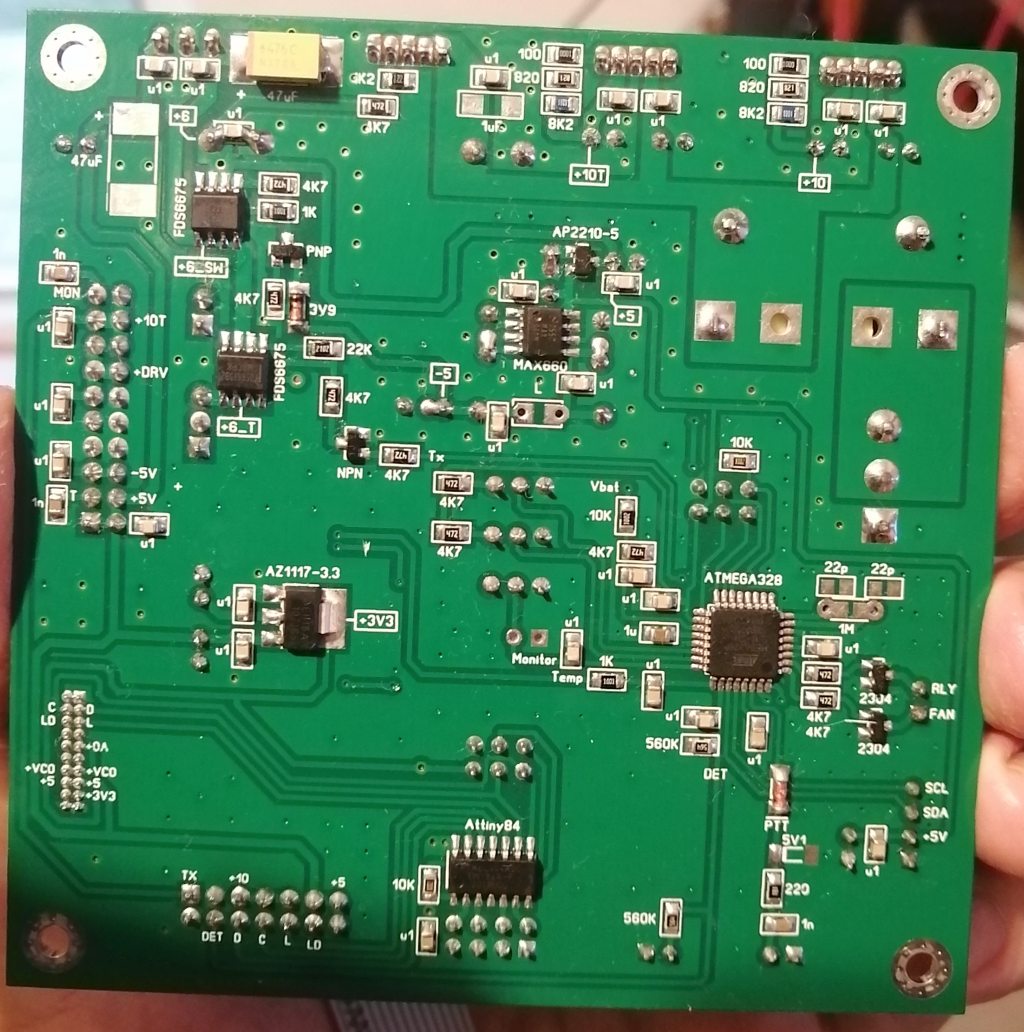
The control part is made with two microcontrollers. I chose this solution for higher flexibility during the experimental phase. One of the microcontrollers deals with temperature monitoring, output power, antenna relay sequencing, fan control and VOX. The thresholds for the fan and RF VOX can be adjusted by means of adjustable resistors. The LCD 2x16 communicates on the I2C, so it is necessary to attach a PCF8574 interface on the rear side of LCD. Of course, the display may be missing without affecting the operation of the transverter.
2nd microcontroller is responsible for programming of both PLLs (ADF4106 LO1 and MAX2871 LO2). It supports various configurations depending of transverter type and intermediate frequency. Jumpers changes take effect only after restart. Tx is inhibited if LO1 & LO2 PLL are not locked. PLL status is indicated on LCD (Lk/Uk).
Main uC firmware will be loaded according the band 5.7GHz or 10GHz, otherwise text band indication on LCD will be wrong (the operation is not affected). PLL uC firmware is universal, configuration according the jumpers selection. The software logic was designed with Visuino and Arduino IDE. Both uC are internaly clocked at 1MHz (PLL uC) & 8MHz (MAIN uC).
Peak power bargraph monitor is a relative reading of forward voltage provided by Alcatel XVRT or by external power amplifier (max. 5V). Full scale is adjusted using "MON" resistor. Temperature indication is according LM50 temperature sensor located inside of XVRT unit.
RF VOX signal is compared by uC. PTT input is also availabe. RF VOX detector is DC coupled with 144/432 input, it is able to detect TX voltage via coaxial cable (DB6NT).
Relay sequenced output has 30msec delay and is suitable to drive RX/TX antenna coaxial relay. FAN output is not very useful but can be used to control a small cooling fan according the setpoint. The cooler is not required if Alcatel XVRT is installed on heatsink or aluminium plate.
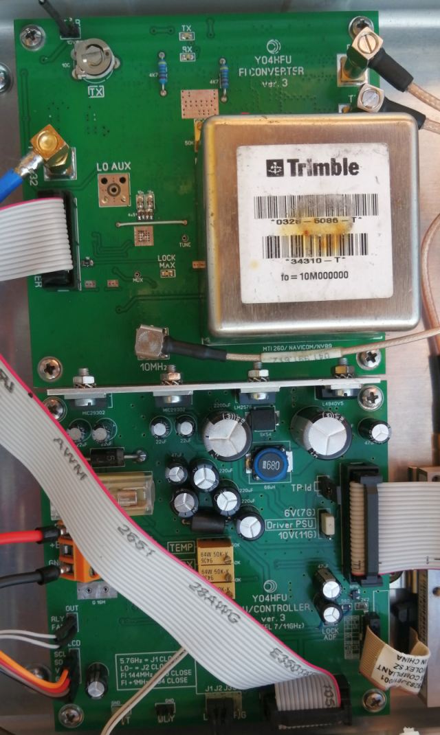
Description of IF Converter Board:
IF board is a heterodyne between RX/TX signal from the Alcatel module and MAX2871 local oscillator. The filtering of the mixing products, the rejection of the image frequency and the leakage of the local oscillator is done using SAW filters. SAW filters are chosen depending on the Alcatel transverter model. As well the LO frequency, low side or high side injection.
Double balanced mixer RMS-25MH is driven with a high level LO (+13dBm) to obtain low intermodulations. The LO level is uniformly adjusted by setting PLL registers according to the frequency planning.
PLL power supply is provided by dedicated low noise LDO regulators on each power bus. The reference oscillator is a thermally stabilized one. Various VCOCXO models can be used. The firmware is designed for 10MHz but of course it can be modified for others, fractional PLL is very flexible. The VCOCXO can be controlled by an external GPS PLL. The experiments demonstrated the excellent stability of the Trimble double thermostat, GPS correction is not required. The reference signal is also injected into the first local PLL Alcatel oscillator, the original TCXO being eliminated.
2nd IF can be 144/145/432/433 MHz by configuring the MAX2871 PLL and 1st Alcatel LO PLL. Maximum recommended input power is 5 Watts. SWR is very good for 144MHz and acceptable at 432MHz due to the parasitic capacitance of SMD power resistors. Reactance compensation was not required. The IF VHF / UHF input is monitored by a galvanically coupled RF detector for DC voltage detection, in the case of over coaxial cable PTT (DB6NT method).
Note: In some places FI abrevation was used instead of IF (Intermediar Frequency).
PS: Counterfeit TPS79333 voltage regulators. Wrong output voltage, bypass capacitor not internal connected to 1.22V band gap reference. Ebay seller top_electronic1980_techwin. Do not buy!
Counterfeit MAX660, not capable to delivery enough output current. No problems using genuine IC. Ebay seller shengmingelectronics. Do not buy!
![]()
![]() PSU/CONTROLLER schematic vers. 3
PSU/CONTROLLER schematic vers. 3
![]() IF CONVERTER schematic vers. 3
IF CONVERTER schematic vers. 3
![]() ADAPTER CONNECTOR schematic vers. 1
ADAPTER CONNECTOR schematic vers. 1
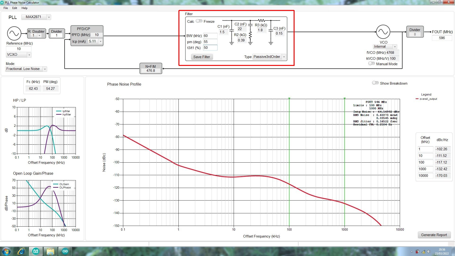
![]() MAX2871 PLL LPF - New values for 10MHz / 5,1mA
MAX2871 PLL LPF - New values for 10MHz / 5,1mA
![]()
![]() PSU/CONTROLLER PCB vers. 4 - (Sprint Layout 6 file)
PSU/CONTROLLER PCB vers. 4 - (Sprint Layout 6 file)
![]() IF CONVERTER PCB vers. 4 - (Sprint Layout 6 file)
IF CONVERTER PCB vers. 4 - (Sprint Layout 6 file)
![]() ADAPTER CONNECTOR PCB - (Sprint Layout 6 file)
ADAPTER CONNECTOR PCB - (Sprint Layout 6 file)
![]()
![]() PSU CONTROLLER view Top and Bottom
PSU CONTROLLER view Top and Bottom
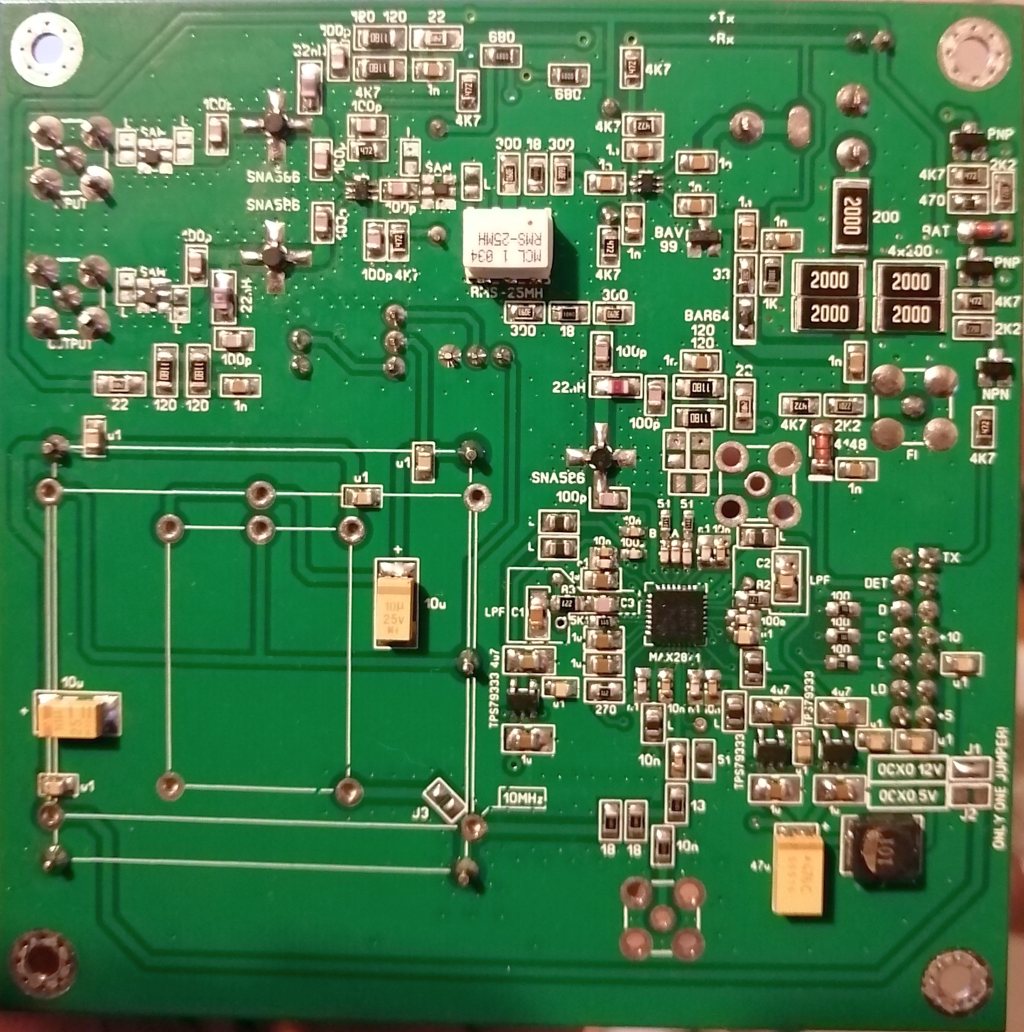
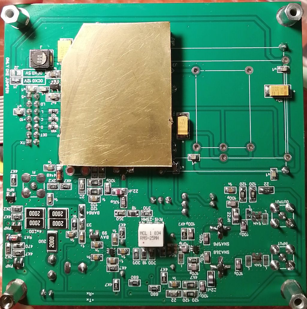
![]() IF CONVERTER view Top and Bottom, Bottom shielded
IF CONVERTER view Top and Bottom, Bottom shielded
![]()
![]() Firmware Attiny84 PLL controller v.15 (default Fuse Bits - 1MHz internal)
Firmware Attiny84 PLL controller v.15 (default Fuse Bits - 1MHz internal)
![]() Firmware Atmega328P main controller v.1: <5.7GHz>, <10GHz>, (Fuse Bits: low_fuses=0xE2; high_fuses=0xD6; extended_fuses=0xFD; 8MHz internal, LCD I2C address 0x27)
Firmware Atmega328P main controller v.1: <5.7GHz>, <10GHz>, (Fuse Bits: low_fuses=0xE2; high_fuses=0xD6; extended_fuses=0xFD; 8MHz internal, LCD I2C address 0x27)
yo4hfu@2010-2026