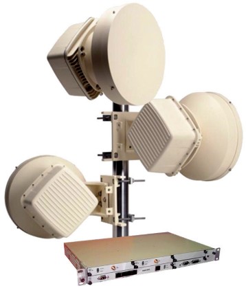
ALCATEL-LUCENT 9500MPR (Microwave Packet Radio) link is available for microwave bands between 6-38GHz.
The 9500 MPR series has several types of ODU (Out Door Unit) wich can be connected by coaxial cable, Ethernet or fiber optic.
Below we will discuss only about ODU300 version (single coaxial cable).
Some specifications extracted from the user manual:
According ODU TX frequency plan, Low or High TX version are available. Example of 11GHz ODU300 found:
TX LOW (Low Band LB), unknown XVRT
Tx:10915-11075 MHz
Rx:11430-1158 MHz
PN: 3DB23035HCAA01
TX HIGH (High Band HB), TR 490-530MHz, MTI XVRT
Tx: 11200-11345 MHz
Rx: 10675-10835 MHz
PN: 3DB23035HEAA02
TX HIGH (High Band HB), EXCELICS XVRT
Tx: 11310-11465MHz
Rx: 10795-10955MHz
PN: 3DB23035HFAA02
ODU 11GHz version is often available on Ebay as decommissioned equipment. Inside of ODU300 next items can be found:
-
Waveguide WR90
-
Duplexer filter coaxial/waveguide
-
XVRT 11GHz E500
- LO PLL
- IF Board 126MHz/311Mhz
- DC/DC converter, -48V
XVRT 11GHz and LO module are the most interesting parts suitable to be reused at 10GHz due to simplicity and excellent quality.
Main RF module XVRT E500 can be found in two versions, manufactured by MTI or EXCELICS. EXCELICS version is difficult to be retuned due to bonding wires and small size microstrip filters.
Other amateurs have reported good results of EXCELICS at 10.368GHz, without any modification: Rx gain 26dB, Pout 1.6W, IF 2320MHz.
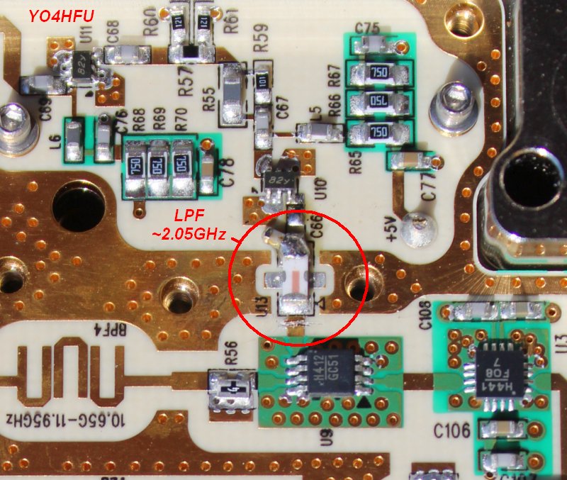
Original Rx 1st IF was found 1600MHz, BW ~90MHz, according measurement of 5 pole ceramic BPF located on IF board. Also the ceramic LPF installed after 1st Rx mixer has cutoff at 2.05GHz.
Then the signal is translated to 2nd IF 311/126MHz. 2nd IF I/O is connected to indoor modulator unit "MOD300" via coaxial feeder. Same coaxial cable is used for -48V power supply and 5.5/4.5MHz telemetry subcarrier.
Tx 1st IF is high pass filtered above 625MHz. Tx IF = [Rx IF] +/- [duplex spacing].
TX driver stage and power stage share same power bus. The voltage can be 7.7V or 10.8V according band frequency range of TRX module. Resistor R6 (not used - "open" for 10GHz MTI) located inside of TRX is monitored by CPU. It coresponding with +7.7V selection for FMM5061 driver & FLM1013-3 PA. The voltage is selected through pin 6 of -48V PSU board. Idle current (gate bias voltage) is automaticaly controlled using closed loop by monitoring FLM1013 drain current. Idle current is programmed according R3, R4 resistors. Control bias for FMM5061 is not used due to internal self biasing from -5V. So resistors R1,R2 are installed only to keep bias circuit not floating. Automatic bias circuit is located on IF board.
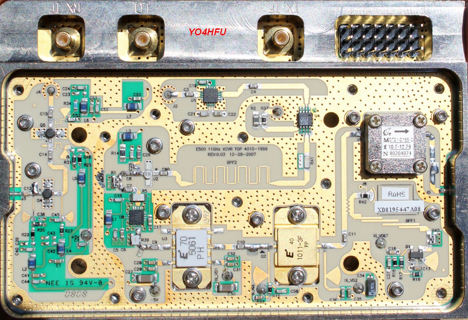
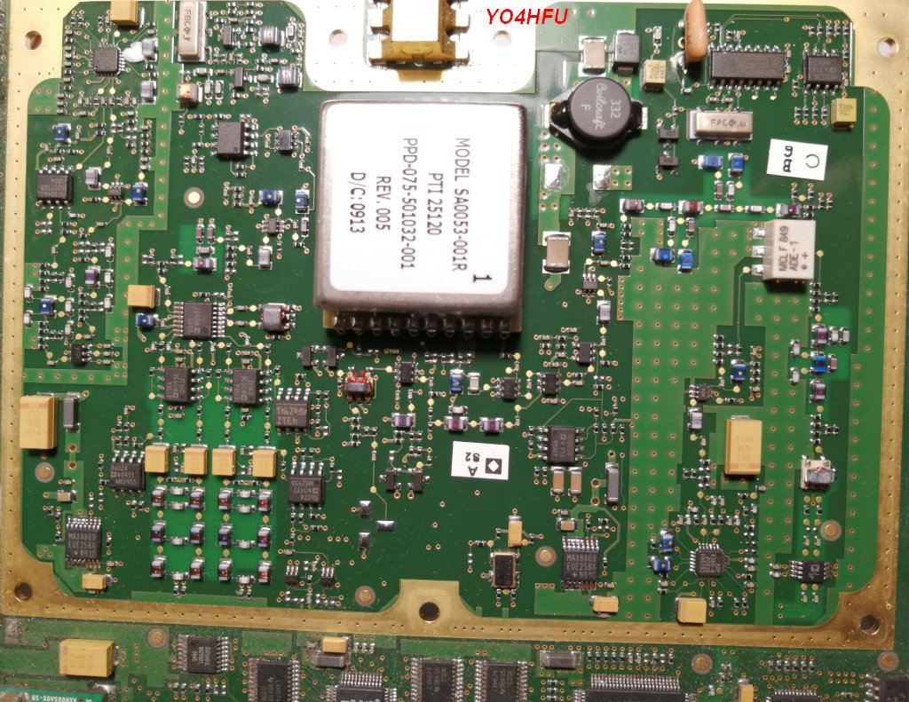
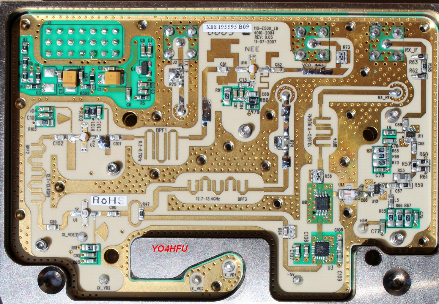
Two versions of MTI E500 XVRT module are available:
![]() 11GHz, Low Band, Hi-side LO Injection, P/N:131-142264-1005-01
11GHz, Low Band, Hi-side LO Injection, P/N:131-142264-1005-01
LO = RF + IF, internal LO multiplier x4 , LO BPF 12.7...13.4GHz. IF output spectrum is reversed (mirror).
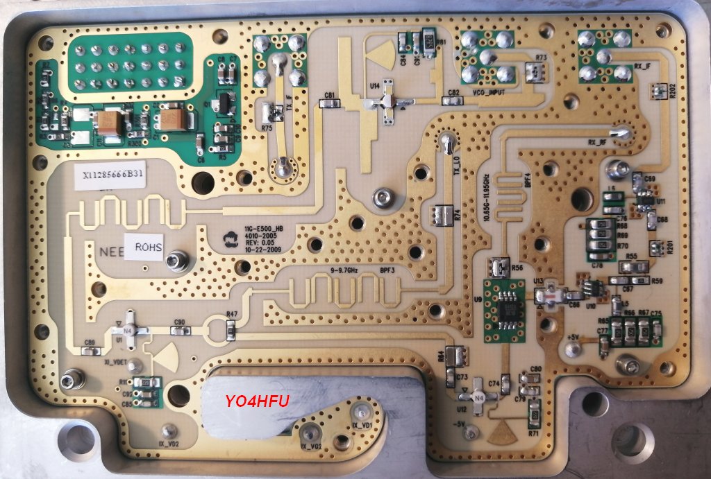
![]() 11GHz, High Band, Low-side LO Injection, P/N:131-142264-1105-01
11GHz, High Band, Low-side LO Injection, P/N:131-142264-1105-01
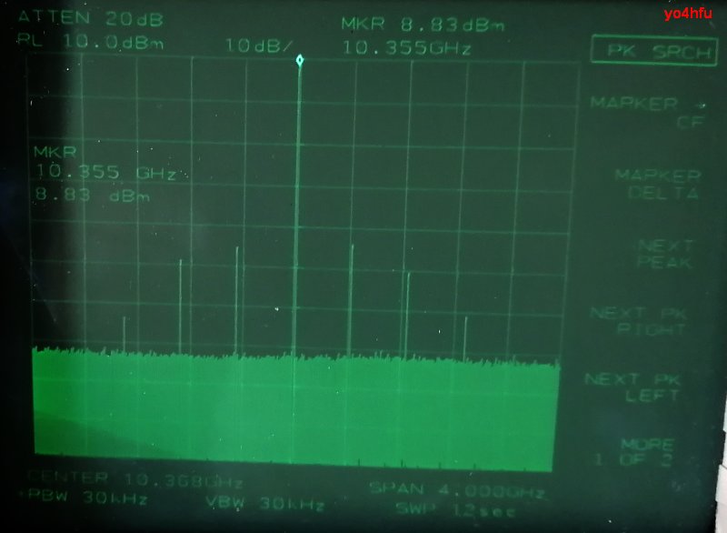
LO = RF - IF, internal LO multiplier x3, LO BPF 9...9.7GHz. More information about Low-side version on IW0FFK website. TX output spectrum using IF 432MHz: -45dBc spurious. RF unit not fully tested.
![]() LO PLL (P/N: 131-142286-007) locking range is 2950-3280MHz, Uvco=Uoa=12V. Some LO boards lock up to 3225MHz at 12V. Optimum settings are CP 0.625mA, PD 1MHz but is able to lock using PD 20KHz...2.5MHz. Output level ~5dBm if supply voltage across VCO terminals is 8V. In order to preserve RF level, VCO limiting resistor R1,R5 must be decreased if external power supply is less than 12V. For 10.5V power supply of VCO, connect 100 ohms resistor in paralel with R1 or R5.
LO PLL (P/N: 131-142286-007) locking range is 2950-3280MHz, Uvco=Uoa=12V. Some LO boards lock up to 3225MHz at 12V. Optimum settings are CP 0.625mA, PD 1MHz but is able to lock using PD 20KHz...2.5MHz. Output level ~5dBm if supply voltage across VCO terminals is 8V. In order to preserve RF level, VCO limiting resistor R1,R5 must be decreased if external power supply is less than 12V. For 10.5V power supply of VCO, connect 100 ohms resistor in paralel with R1 or R5.
***
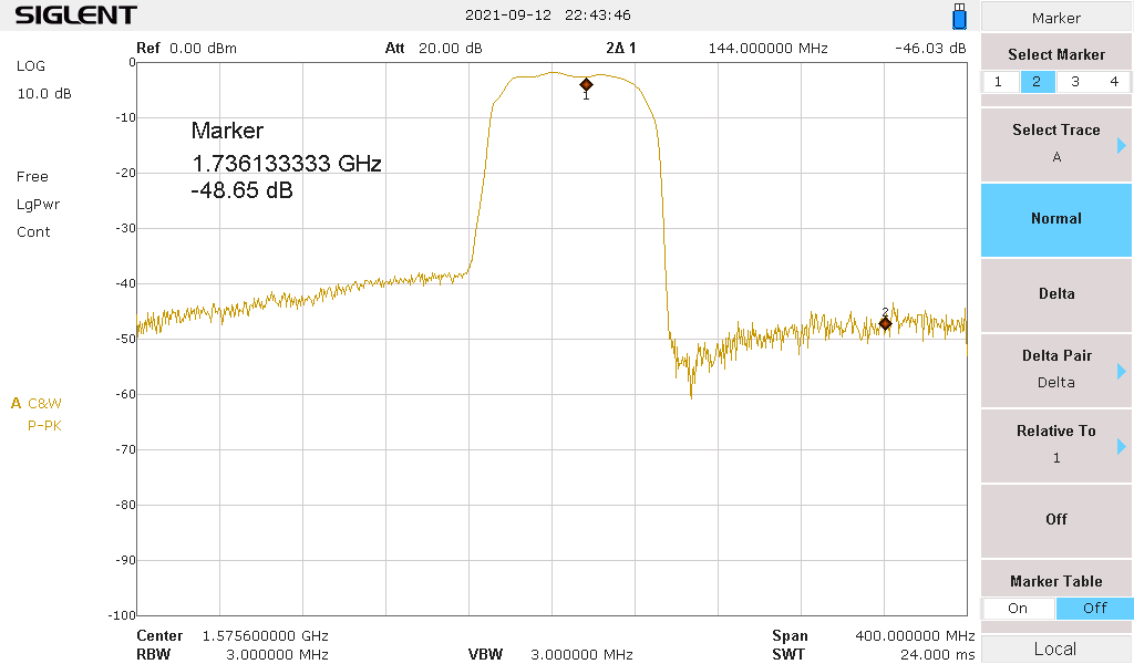
Let's see frequency planning for 1st IF 1592MHz and 1218MHz. Optimal IF for 10.368GHz can be ~1500MHz. The most common SAW filters available are designed for GPS use.
HIGH SIDE LO, LO x4, LB Xvrt P/N:131-142264-1005-01 * TESTED
RF = 10368MHz
LO1 = 10368MHz + 1592MHz = 11960MHz
Fimg = 11960 + 1592 = 13552MHz
LO1 VCO = 11960 / 4 = 2990MHz - 1st IF SAW GPS 1582MHz, BW 80MHz, F6QA1G582H2JM-J, excellent image/LO rejection or SF2353E (more easy to solder)
LO2 = 1592 + 144 = 1736 MHz (spectrum direction restored)
LO2 = 1592 + 432 = 2024 MHz
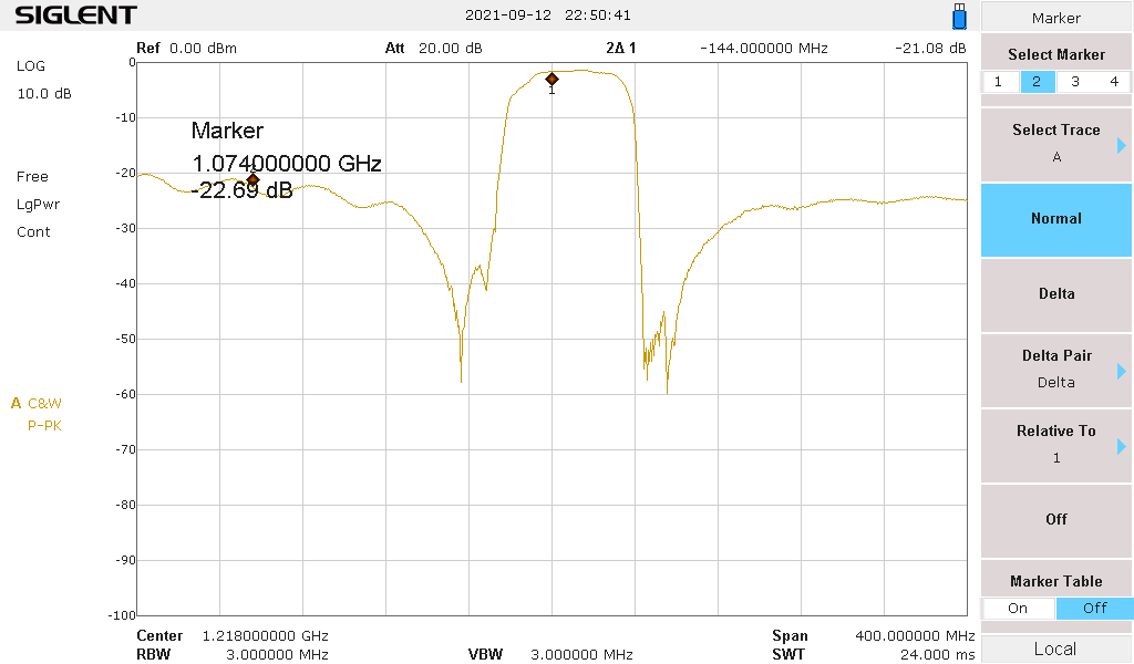
LOW SIDE LO, LO x3, HB Xvrt P/N:131-142264-1105-01
RF = 10368MHz
LO1 = 10368MHz - 1218MHz = 9150 MHz
Fimg = 9150 - 1218= 7932MHz
LO1 VCO = 9150/ 3 = 3050MHz - 1st IF SAW GPS L2 1227MHz, SF2208E. 1st IF higher than 1500MHz is not possible due to out of range PLL.
LO2 = 1218 - 144 = 1074 MHz
LO2 = 1218 - 432 = 786 MHz
Original IF board is difficult to be reused at 144MHz or 432MHz. I designed a new controller, IF convertor and PSU which can support various Alcatel 9500 XVRTs.
See Alcatel IF Converter/Controller project.
![]()
![]() XVRT MTI LB 11GHz conversion to 10GHz rev.4
XVRT MTI LB 11GHz conversion to 10GHz rev.4
![]() XVRT 11GHZ MTI schematic rev.1.5 (reverse eng.), Hi-Side LO
XVRT 11GHZ MTI schematic rev.1.5 (reverse eng.), Hi-Side LO
![]() LO PLL schematic rev.1.4 (reverse eng.)
LO PLL schematic rev.1.4 (reverse eng.)
![]() XVRT MTI top
XVRT MTI top
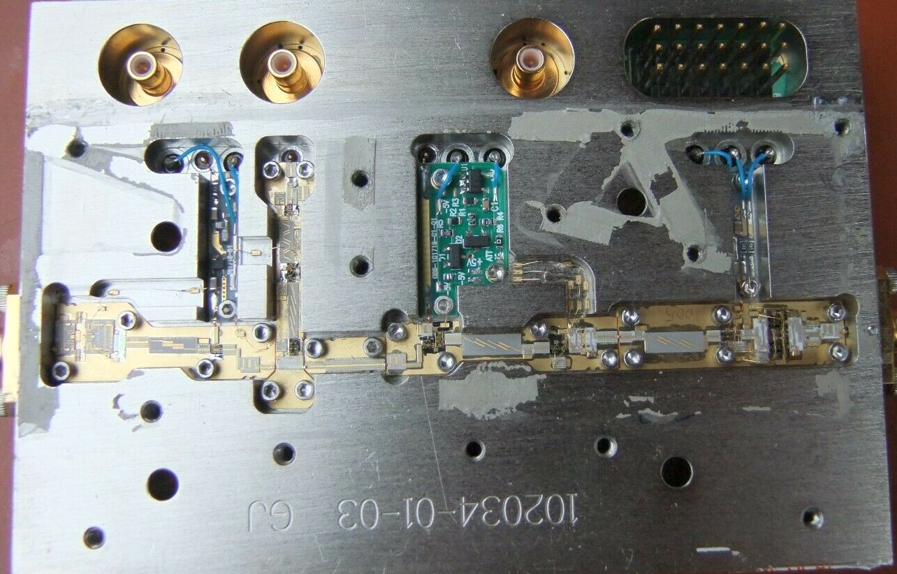
![]() XVRT MTI bottom
XVRT MTI bottom
![]() XVRT EXCELICS 11GHz
XVRT EXCELICS 11GHz
![]() LO PLL
LO PLL
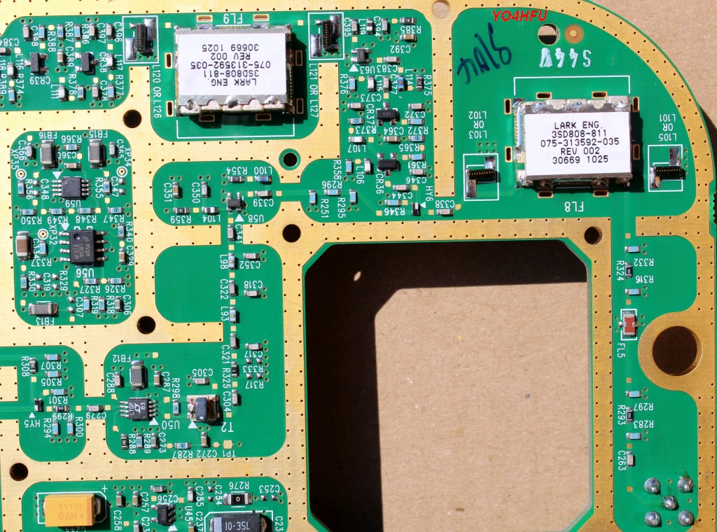
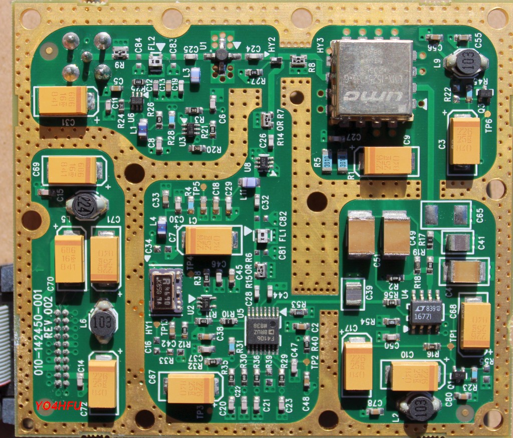
![]() IF Board top
IF Board top
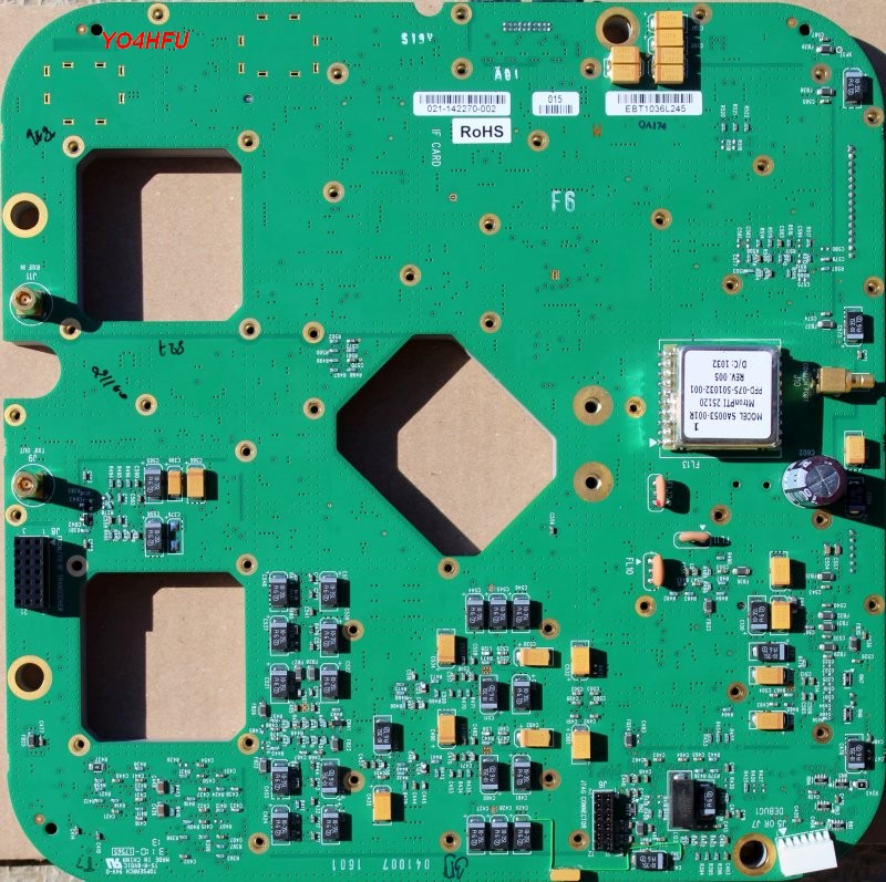
![]() IF Board bottom
IF Board bottom
![]() IF Board - 1.6GHz Rx IF filters
IF Board - 1.6GHz Rx IF filters
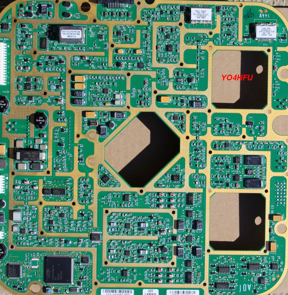
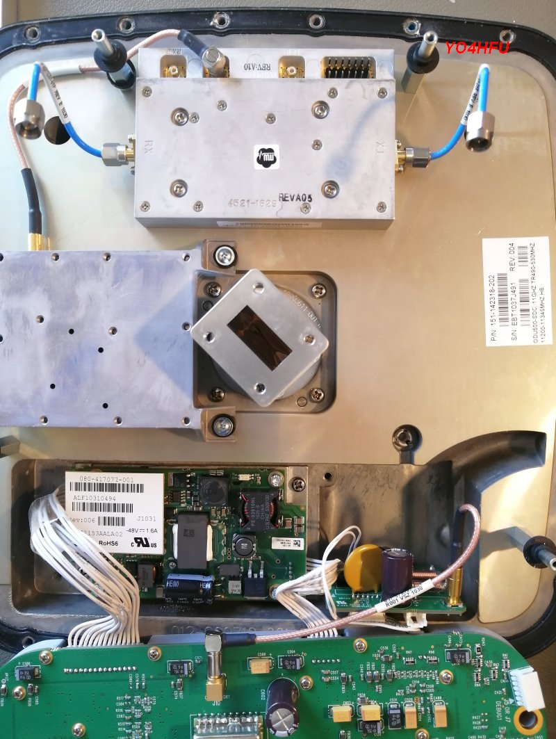
![]() ODU-300 internal view 1
ODU-300 internal view 1
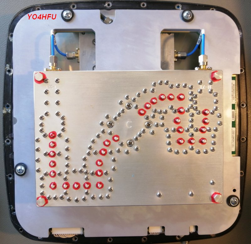
![]() ODU-300 internal view 2
ODU-300 internal view 2
![]() IDU MOD-300, RF block
IDU MOD-300, RF block
yo4hfu@2010-2026