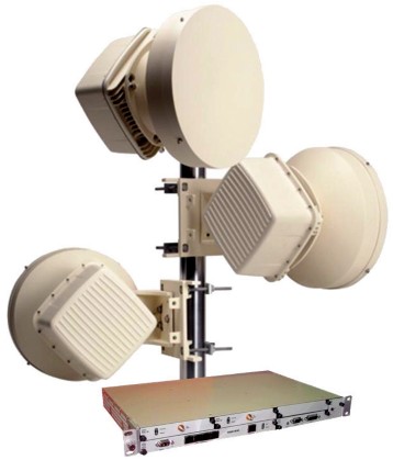

ALCATEL-LUCENT 9500MPR radio link are available for many microwave bands between designed for 7GHz were available on Ebay as decommissioned equipments. Inside of ODU-300 (Out Door Unit) next items can be found: wave guide, duplexer filter, XVRT 7GHz, LO, FI Board and PSU -48V. XVRT 7GHz and LO modules are the most interesting parts suitable to be reused at 5.7GHz due to simplicity and excellent quality.
XVRT E500 module can be found in two versions, manufactured by MTI or EXCELICS. Version made by EXCELICS is difficult to be retuned due to bonding wires and small size microstrip filters.
According ODU TX frequency plan, Low or High TX version are availabe. Example of 7GHz ODU-300:
TX LOW
Tx: 7107-7191 MHz
Rx: 7303-7387 MHz
ODU500 TR 169MHz
PN: 3DB23188AAAA01
XVRT EXCELICS STRATEX E500, P/N: 131-142264-1003
LO P/N: 131-142286-007
TX LOW
Tx: unknown
Rx: unknown
PN: unknown
XVRT E500 MTI, P/N: 131-142264-1003-01
LO P/N: 131-142286-007
TX HIGH
Tx: 7611-7695 MHz
Rx: 7443-7527 MHz
ODU500 TR 161/168MHz
PN: 3DB23186HBAA01
XVRT E500 MTI, P/N: 131-142264-1103-01
LO P/N: 131-142286-008
Original Rx 1st IF was found 1600MHz, BW ~90MHz, according measurement of 5 pole ceramic BPF located on IF board. Also the ceramic LPF installed after 1st Rx mixer has cutoff at 2.05GHz.
Then the signal is translated to 2nd IF 311/126MHz. 2nd IF I/O is connected to indoor modulator unit "MOD300" via coaxial feeder. Same coaxial cable is used for -48V power supply and 5.5/4.5MHz telemetry subcarrier.
Tx 1st IF is high pass filtered above 625MHz. Tx IF = [Rx IF] +/- [duplex spacing].
TX driver stage and power stage share same power bus. The voltage can be 7.7V or 10.8V according band frequency range of TRX module. Resistor R6 (0 ohm - "closed" for 7GHz MTI) located inside of TRX is monitored by CPU. It coresponding with +10.8V selection for FMM5057 driver & FLM7179-4 PA. The voltage is selected through pin 6 of -48V PSU board. Idle current (gate bias voltage) is automaticaly controlled using closed loop by monitoring FLM7179 drain current. Idle current is programmed according R3, R4 resistors. Control bias for FMM5057 is not used due to internal self biasing from -5V. So resistors R1,R2 are installed only to keep bias circuit not floating. Automatic bias circuit is located on original FI board.
Two versions of MTI E500 XVRT module are available:
![]() 7GHz, Low Band, Hi-side LO Injection, P/N:131-142264-1003-01
7GHz, Low Band, Hi-side LO Injection, P/N:131-142264-1003-01
LO = RF + IF, internal LO multiplier x3 , LO BPF 8.8...9.7GHz. IF output spectrum is reversed (mirror).
![]() 7GHz, High Band, Low-side LO Injection, P/N:131-142264-1103-01
7GHz, High Band, Low-side LO Injection, P/N:131-142264-1103-01
LO = RF - IF, internal LO multiplier x2, LO BPF 5.3...6.3GHz.
1st IF of MTI 7GHz HB conversion to 5.7GHz is 740MHz due to available SAW filter (B39741B9480M410). The signal is down converted to 144 or 432MHz by home made IF converter. Also the power supply and control are integrated. For more details see "IF Converter/Controller for Alcatel ODU".
![]()
![]() XVRT MTI HB 7GHz conversion to 5.7GHz rev.1
XVRT MTI HB 7GHz conversion to 5.7GHz rev.1
![]() XVRT 7GHZ MTI LB schematic rev.1.3 (reverse engineering)
XVRT 7GHZ MTI LB schematic rev.1.3 (reverse engineering)
![]() XVRT 7GHZ MTI HB schematic rev.1.3 (reverse engineering)
XVRT 7GHZ MTI HB schematic rev.1.3 (reverse engineering)
![]() LO PLL schematic rev. 1.4 (reverse engineering)
LO PLL schematic rev. 1.4 (reverse engineering)
![]() 7GHz MTI LB top
7GHz MTI LB top
![]() 7GHz MTI LB bottom
7GHz MTI LB bottom
![]() 7GHz MTI HB top
7GHz MTI HB top
![]() 7GHz MTI HB bottom
7GHz MTI HB bottom
![]() EXCELICS
EXCELICS
![]() LO PCB
LO PCB
![]() IF Board top
IF Board top
![]() IF Board bottom
IF Board bottom
![]() IDU MOD-300
IDU MOD-300
![]() 5.7GHz XVRT using Alcatel 7GHz and FI/Controller board
5.7GHz XVRT using Alcatel 7GHz and FI/Controller board
![]() 5.7GHz XVRT front panel
5.7GHz XVRT front panel
![]() PA 35W 5.7GHz
PA 35W 5.7GHz
![]() Fake FLM5964-18 China, Open package, Fake Eudyna certificate (almost normal idle current but no RF gain) - Ebay seller xihu888
Fake FLM5964-18 China, Open package, Fake Eudyna certificate (almost normal idle current but no RF gain) - Ebay seller xihu888
![]() Genuine TIM5964-35, Genuine Toshiba certificate - output power >35W
Genuine TIM5964-35, Genuine Toshiba certificate - output power >35W
![]() Coaxial relay melted at 35W/5.7GHz, Relay type (not PTFE)
Coaxial relay melted at 35W/5.7GHz, Relay type (not PTFE)
![]() Overcurrent protection BTS550 and 12/28V step up, Bottom view, Schematic (used to power off the transverter in case of PA overcurrent - high SWR)
Overcurrent protection BTS550 and 12/28V step up, Bottom view, Schematic (used to power off the transverter in case of PA overcurrent - high SWR)
![]() 5.7GHz 1st QSO test
5.7GHz 1st QSO test
![]() Video 5.7GHz QSO, QRB 190Km with YO3CYR (link to home made transverter)
Video 5.7GHz QSO, QRB 190Km with YO3CYR (link to home made transverter)
yo4hfu@2010-2026