N9EWO Review : Japan Radio Company [JRC] NRD-525 Communications Receiver.
3 Samples were tested for this report
Country Of Manufacture : Japan
Serial Numbers of Test Samples :
#1 : 3812x
#2 : 3829x
#3 : 4372x
Accessories Tested :
#3 sample - CMK-165 VHF-UHF converter (consists of two PC boards, two SO-239 connectors).
NVA-88 Matching External Speaker (2).
Firmware Versions Tested : Unknown
Test Antenna's :
- Included 25 inch telescopic whip
- Short 20 foot [6 meter] indoor wire antenna
- Comet DS150S Discone Antenna (30 foot [10 meter] height)
- RF Systems MLBA-MK2 long wire (55 foot length [16.7 meter] - 24 foot [7.3 meter] height at peak)
- Comet H-422 Dipole 31 feet [9.4 meters] in length (24 foot [7.3 meter] height) - Straight Configuration)
Discontinued Receiver
PRO :
- Fully modular construction.
- Uses surface mount components except and thankfully NOT using surface mount electrolytic capacitors.
- Excellent Sensitivity.
- Excellent Selectivity (3 bandwidths available stock).
- Excellent Stability with 3ppm TXCO (included as stock not an option).
- Good ECSS (see con).
- Very Good Image and Spurious Signal Rejection.
- Very Good Dynamic Range.
- Excellent IF Notch Filter.
- Above Average Noise Blanker.
- All Tuning Methods Including Up-Down Slewing.
- Extremely Smooth Optical Type Main Tuning Encoder.
- Top Drawer Ergonomics.
- Pass Band Shift control works in all modes including AM.
- All buttons have above average tactile feel (see con).
- Extremely quiet AC power transformer.
- Generally just warm operation at 100 / 117 VAC (reports indicate runs hot at 220/240 VAC, not tested).
- 200 tunable memory channels that store frequency, mode, bandwidth and attenuator (see con)
-
Stock "AUX" superwide 12~14 kHz IF "defacto" bandwidth cures the
NRD-545's woofy audio in AM mode (with the right external speaker).
- 20 db attenuator.
- Accurate digital "Bar" S-Meter (so be it being a bit jumpy).
- RIT for quick small frequency adjustments.
- Can also be powered on 13.8 VDC.
- 1 event timer / 2 time zone clock (see con).
- Scanning of memory channels or VFO.
- Beep and line audio output level adjustment's are easily accessible on cabinet bottom (no need to remove covers, see con).
- High cut off tone control.
- Medium Wave Band NOT deliberately attenuated (full sensitivity).
- Good performing all mode squelch control.
- Main tuning knob does NOT use a rubber track around it (no old age deterioration).
- 3 step dimmer plus OFF for florescent display and front panel LEDS (see con).
- Low distortion detector gives for clean SSB and AM mode audio (see text).
- CMK-165 (2 boards) VHF-UHF converter option works decently (see con).
CON :
- Can be IF hissy, the worst on narrower bandwidths and is variable depending on sample (see text).
- AM audio is still "woofy" with narrower bandwidths (proper 2 way external speaker helps this to an extent).
- Internal speaker is a downright stinker.
- Clock shared with main Frequency.
- Carousel AGC, bandwidth and mode selections.
- Tuning knob tunes no faster than extremely poky 100 hz steps (early production samples only tuned ultra poky 10 hz steps).
- Battery backed memory channel data (soldered in CR2023 battery with solder tabs).
- No front cabinet riser feet.
- Numeric keypad buttons have long travel to activate.
- Only one VFO.
- Variable controls can become scratchy / dirty (old age issue).
- Front panel tact buttons can become intermittent (old age issue).
- Main fluorescent displays are known to become weak or quit altogether in it's old age.
- ECSS compromised by a coarse 10 hz tuning step.
- Rear antenna switch is prone to become intermittent (easily fixed, see text).
- No display indication of Noise Blanker, Notch or PBT when in use.
- Many user defined settings not available on early production (see text).
- Flimsy ON-OFF-TIMER switch.
- Display when in the 2 dimmest settings, annoyingly "pulsates - flickers" (see text).
- Bottom feet can turn a bit sticky in it's old age.
- When using STEREO headphones, sound is out of phase. (see text).
- Tuning knob uses a fixed dimple (does not rotate).
- Beep and line audio output level adjustment's on bottom use very small screwdrivers and is fragile / touchy to do.
- Optional RS-232 serial port operation.
- CMK-165 (2 boards) VHF-UHF converter option performed best on the VHF frequencies (with test sample).
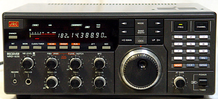
Solid Modular Construction (except for painted plastic front bezel) / 13.8 VDC Operation
The
Japan Radio Co. (JRC) NRD-525 size is 13 x 5.2 x 11.25 inches (330 x
130 x 280 mm) and weight is 20 pounds (8.5 kg) with no options installed. So is a large, heavy
and beefy size modern solid state tabletop consumer grade table top
receiver.
As normal for most (but not all) JRC sets it is powered with a internal
multi voltage AC power power supply (100/120/220/240 VAC 50/60 Hz).
Unlike the previous NRD-505 and NRD-515 models, the 525 can also be
powered from 13.8 VDC (at around 2 amps max).
Fully modular construction with a main mother board and slide in
daughter boards. Steel outer cabinet and black painted aluminum rear panel.
Sadly the front bezel is painted thin plastic which is quite fragile
(including the painted surface). The use of surface mounted components
are used throughout in the 525. Good news here it does NOT contain
any surface mounted type electrolytic capacitors.
Nice QUIET Internal AC Power Transformer / Only Runs Warm at 117VAC / Jiggly ON-OFF-TIMER Switch
This receiver
uses NO nasty switching power supplies (fully linear) and the internal
AC power transformer creates no mechanical hum PERIOD even with the
number three 30+ year old test sample. It's absolutely dead quiet to
our ears even at twelve o'clock midnight. This is so rare even back
when it was manufactured. I'm sure many have experienced the Drake R8
series poor quality HOT power transformers that can buzz like crazy
even when off in stand by mode (or with the later production NRD-545's).
Equally important is the power supply has totally clean outputs. No hum
PERIOD emitting from it's audio amplifier. This is of course going to
be dependent if all electrolytic power supply capacitors are in good condition.
Not only is the power transformer super quiet with the receiver ON or
in stand by OFF mode, but runs only warm (at cooler ambient room
temperatures). As as tested at 117 VAC USA mains. It has been reported
over the years that it's operates a tad hotter at 220/240 VAC (not
tested). Ditto for the power supply transistors / regulators that are
mounted to the rear cabinet. Can easily touch that area / mounting
screws with fingers even if in operation for a number of hours. That is
something that is not done by accident, careful design at work here.
However something that was not well designed is the main POWER-timer
toggle switch. Even as new it had an excessively jiggly low grade feel.
With years of use this feeling gets worse or the switch just fails. JRC
continued to use this type of switch with future models including the NRD-345, 535 and 545 (click here for our
NRD-545 review).
Excellent
Ergonomics (except tuning knob speed) / Silky Smooth Optical Encoder /
Tactile Button Feel / Important Serial Number Data
Overall layout
of all controls and buttons are ergonomically excellent. All
pushbuttons have a good tactile feel and uses actual springs on each
button (except for the Bandwidth, Mode and Up-Down slewing) for return
tension. This is a much better way of doing it over say using felt or
foam that would deteriorated by now (or using none at all). Only
downside is the numeric buttons have a considerable travel gap before
hitting the actual tact switches.
Carousel
up-down selection of the MODE, BANDWIDTH and AGC spoil the ergonomics a
bit. All tuning methods are available. Numeric keypad with standard
telephone format. Scanning feature that works with the memory channels
or VFO. These scan features worked well when properly set up (speed and
pause level are front panel adjustable).
JRC used a Copal optical encoder for the main knob tuning and is
silky
smooth and has a flywheel effect (has a weight inside of it). Plastic
knob uses set a set screw for attachment to the encoder and does NOT
make use of rubber ring around it. With the NRD-525's age, using a
rubber ring here will have most likely deteriorated to an extent by
now. But not to worry
here as it uses none. The spinner hole does not have a rotating piece
to it (fixed dimple), unlike the Icom IC-7300 that does (see our review
here).
Only major bug-a-boo with the 525's tuning knob is the poky tuning steps used. It's disconcertingly S-L-O-W
even at the faster 100 hz step. If you have early production sample,
it's much worse only having a lone 10 hz tuning knob step ! The flywheel
effect helps but only to an extent As of writing this report Christophe F4EZC in France is offering updated EPROM firmware he wrote that adds MANY additional tuning knob / slewing button steps (see manual here)
that should speed things up nicely (not tested). PLEASE NOTE : This upgraded EPROM also REQUIRES IF filter modifications / major hardware
changes that are not for the faint of heart (advanced soldering skills
required). For more information and pricing via email (from France) please click here.
F4EZC : JRC CPU EPROM Versions
I will NOT be held responsible for any info that is listed here.
ALL DONE AT YOUR OWN RISK ! |
| JRC NRD-525 Important Serial Number Information |
If you are looking at a used Japan Radio Co. (JRC) NRD-525
Communication Receiver, here is very important serial number data
to keep in mind.
JRC NRD-525 "Serial Number" History
(NRD-525 EPROM Firmware is not easily or possible to be updated, see above text.)
- BR36471 (and above) SSB offset selection added
- BR36771
(and above) The tuning rate of the main tuning knob and the step
increment of the UP and DOWN switches can be changed by hitting the RUN
button. Selects the desperately needed 2 tuning knob speeds
between 10 Hz or 100 Hz steps. The UP / DOWN slewing buttons toggle
between 20 kHz and 10 kHz. Early samples only have a single VERY POKY
and extremely frustrating 10 Hz tuning knob step.
- BR38301 (and above). The last important firmware update / bug fixes JRC did with the NRD-525.
|
JRC NRD-525 User Defined Settings
|
* MEMO pressed / held, then press
|
User Defined Setting
|
* 0
BR36471 (and above)
|
1.5 kHz
SSB Offset
ON / OFF
|
* 1
|
10 hz Display Digit
ON / OFF
|
* 2
|
Clock Colon Blinking
ON / OFF
|
* 3
|
Keypad Beep
ON / OFF
|
* 4
|
Front End Filters ON / OFF
|
RUN
(in FREQ mode)
BR36771
(and above)
|
Tuning Step
KNOB (all modes) :
10 / 100 hz
Slewing Buttons :
1 / 10 kHz
FM : 5 / 10 kHz
|
Excellent Sensitivity / Selectivity / Stability (that includes a STOCK 3 ppm TXCO / Display Accuracy
NRD-525's
sensitivity is excellent. It equals the Icom's IC-R8600 for the most
part in testing. If the preamp is used in the R8600, then the
Icom beats the race (along with added noise floor). But no one should
use the IC-R8600 preamp normally below 15 MHz with proper outdoor
antennas anyway.
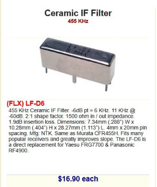
Stock IF bandwidth filters include a plastic cased Kokusai MF-31C MECHANICAL at
around 2.3 kHz (INTER FL4), a metal cased NTK CLF-D6S ceramic at around 6 kHz
(WIDE FL3) and a open 455 kHz "no filter" spot in the AUX slot that gives a nice
wide 12 to 14 kHz bandwidth. This wide bandwidth is actually determined by the pre-roofing filter FL2 which is a NTK LF-B12 (12 to 14 kHz). This of course gives the best audio quality
for AM mode broadcast signals (more on this later). Filters are all totally independent of mode.
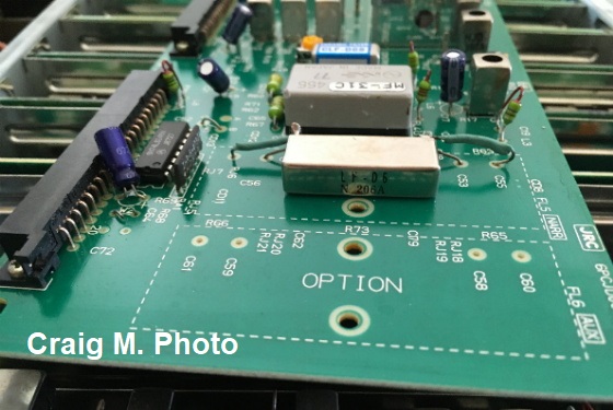
Test sample had a added approx.
8~9 kHz (real bandwidth) added metal cased NTK
LF-D6 ceramic filter in the NARR (FL5 position). This is a excellent added filter between the 6
kHz and 12~14 kHz slots. As of writing this report this filter
is available from "Surplus Sales of Nebraska" in the USA (subject
to change and may be sold out as you read this, also note is a $ 25. USD minimum order requirement). Good news here is
no additional parts were needed for the filter to work properly with
the NRD-525, so no
impedance matching issues being it's a NTK manufacture. Just a bit strange side placement and wiring as shown in the
photo below.
I will NOT be held responsible for any info that is listed here.
ALL DONE AT YOUR OWN RISK ! |
Fluorescent Display "Pulsates - Flickers" When Dimmed
Custom made
Fujitsu fluorescent display has
four display settings (OFF - Low -
Medium - High). With the # 3 test sample when in the Low and Medium
settings it annoyingly "pulsates - flickers" (been too long ago to say with # 1
and # 2 test
samples). Intensity of this varies and is not as bad in the
Medium setting. This is a issue when cold or fully warmed up (does not matter). There is
no trace of this in the High position at any time. Not sure if this
relates to old age, in it's design, a bit of both or just my eyes ?
Please see my
general warnings with these ever aging fluorescent displays at the
bottom of this page.
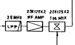
Dynamic Range / Front End RF Amplifier Using Balanced Design
The
NRD-525 uses two 2SK125 FET first and second balanced mixers in it's
design. Even better is also using a balanced (also two 2SK152 FET's) RF
amplifier before
the 1st mixer. This was unheard of with consumer / amateur grade HF
tabletop receivers / transceivers in the day (and even now). The later
NRD-535
model improved on this concept using four FET's on all of these bases.
Of course this greatly helped the receivers
decent dynamic range. We never heard any traces of overloading in
testing with all 3 samples (outdoor antenna's as listed above).
Very Good Image and Spurious Signal Rejection / Tracked Front End Filters / Front End Filters Can Be Bypassed.
Mind
you there still could be a spurious signal here and there that pops up,
but detected no stray out of place signals in testing. In the HF
coverage of the receiver there are 9 front end bandpass filters. These
front end filters can also be defeated using a user defined setting
(see above chart). PASS is indicated on the florescent display in red
when bypassed.
Also in the 525's front end filter also makes use of varactor diodes
that create a double tuned circuit (A.K.A. : tracked tuned) to help the
front end selectivity even more.
A 20 db attenuator is provided. We never needed to use it for any
overloading issues, but is nice to have for those very local signals say a
nearby amateur radio operator you are listening to,
| JRC NRD-525 Front End Bnadpass Filters |
0.090 to 0.399 MHz
|
0.400 to 0.799 MHz
|
0.800 to 1.599 MHz
|
1.600 to 2.649 MHz
|
2.650 to 4.399 MHz
|
4.400 to 7.399 MHz
|
7.400 to 12.299 MHz
|
12.300 to 20.499 MHz
|
20.500 to 33.999 MHz
|
All Mode PBT and Notch That Work Well / Possible ECSS - But Only a 10 hz Minimum Tuning Step
Not
only do we have a excellent "Pass Band Tuning" control (PBT), it also
works in all modes to help tweak the AM mode audio a bit. IF Notch
feature works in the IF and is also a stellar performer.
The only snafu with both
of these features is there is no indication that they are in use on the
florescent display. This oversight was cleared up on the later
NRD-535(D) model.
ECSS is more than possible and with it's excellent stability CAN work
well here. Sadly having only a 10 hz minimum tuning step means you have
a one in ten chance of proper phasing to sound correct. As it always
goes here, If one keeps the bandwidth more narrow any slight out of
phase sound will be less noticeable. But we found ECSS to be most useful
anyway.
Audio Quality / Syncrophase Detector ? / IF Hiss / External Speaker a MUST (forget the NVA-88 Matching Speaker)
It
is well known that the NRD-515's AM mode audio quality was downright
awful ! Was no easy way to help that either using wider bandwidth filters.
So one had to resort to use ECSS mode to fight the muffled audio gremlin.
With the NRD-525, there are 3 stock included out of the box IF
bandwidth filters (see above for details). When the super wide
12~14 kHz "no filter" setting in AM mode, AND when connected to the RIGHT external speaker. The
what we all "woofy" sound and IF hiss found in narrower bandwidths is
just about totally gone ! What we used in testing and gave this
excellent result was with our reference Realistic Minimus 7 and 77
speakers. These speakers even gave a good bass boost kick. We tried
a few other smaller hi-fi speakers and came up with no real
improvement.
We tested a
couple for the matching NVA-88 speakers over the years and while it was
OK, does NOT help improve the audio over what the Realistic Minimus
7 and 77 speakers do. By the way even if the 525 has a internal speaker
(the NRD-505 and NRD-515 have none), don't expect to use it for other
than testing it out to see if it works OK. It's just downright awful as
most internal ones are, but this is one that is downright lousy !.
IF hiss is another well known trait with the NRD-525. However and has
been said elsewhere, this bug can vary greatly from a sample to sample
(later ones tend to be more constant in this regard having a less hissy
trait). With our first two test samples IF hiss was nasty bad. The
narrower the IF bandwidth the worse it was. With test sample # 3 with
it's much higher serial number, fared MUCH better in this regard, in fact it was hardly noticeable !
Instead of using a standard single diode AM detector and quad diode product detector for SSB. JRC used a SN16913P "Double Balanced Mixer"
Integrated Circuit (IC) for both modes. This gives for low distortion performance as
used for detector circuits. Some have said over the years this gave AM mode giving
Synchronous Detection with the NRD-525 which it clearly does NOT ! Using the the term Synchophase Detection is more valid (but perhaps not absolute). Anyway, this gives for much cleaner and lower distortion AM
detection over the NRD-515 and single diode AM detectors.
Good Digital S-Meter / RS-232 Operation / Noise Blanker a Bit Above Average
Electronic
bar graph S-Meter is involved with the florescent display. No
mechanical type used here. It's works well, most accurate as far as we
can measure in comparisons with other table top sets at HQ. Some may call it
as jumpy as grasshopper in a wheat field. But we found to be
pleasurable and useful.
CMH-532 option allow RS-232 operation (not tested). Good luck obtaining
one on the
used market as those are pretty rare these days. Rear panel connector
is a nonstandard 25 pin disaster, but that can be expected considering
when the receiver was developed. To make matters even worse the
nonstandard 6ZCJD00140 connecting cable was sold separately. JRC made
RS-232 more user friendly with the NRD-535(D) using a standard DB-25
connector and was no longer an option.
Variable noise blanker performs a bit above average, but don't expect to perform miracles.
200 Memory Channels / Memory Data is Battery Backed
Previous JRC
NRD-515 model used a external unit to provide user defined memory
channels. NDH-515 for 24 channels and the later NDH-518 model increased
that to 96 channels (24 x 4). These devices only stored frequency (not
even the mode). With the NRD-525 memory storage was made internal and
increased to 200 channels that not only stored the frequency but mode,
IF Filter, AGC and attenuator settings.
Downside is the memory channel data is using a battery backed system.
Battery type is still using the common CR-2032 type and is easily
accessed due to it's modular design (provided you have a set of
those nifty board puller-lifters). It's uses a bit now nonstandard
spaced solder tabs. But should not be hard to retro that to make work
when it fails to store memory channel data.
Thank goodness the battery does not effect the operational side of the
receiver unlike with the Icom IC-R71A (see our review here).
Line Output and Keyboard Beep Levels Accessible From Cabinet Bottom
Don't
like the key BEEP being so loud or the Line Audio output being bit too
hot. JRC made for easy adjustments located and marked on the bottom of
the cabinet with both of these, so you do not have to remove the bottom
cover. WARNING NOTE :
These adjustments are deeply recessed and takes a very small jewelers
metal blade screwdriver. One needs to take extra care adjusting these
as they have a very small slot on the variable controls and if not
correctly could easily damage them.
Excellent that JRC provided both of these adjustments. With all test
samples the BEEP required a lower setting (to our ears) whereas the
LINE output needed adjustment up to be at a proper level with external
recorders.
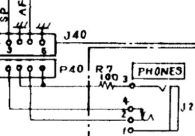
Headphone Jack Wired Out of Phase
This bug has been covered elsewhere over the years, but for the record. The NRD-525's headphone
jack is wired out of phase when stereo headphones are used. One side
sounds way off in the distance ! You can clearly see in the schematic
below that shows why this is. Sadly JRC went cheap here instead of
using the proper jack. Another one that was cleared up with future JRC
receiver models.
Way around this issue is
to just make use of a external stereo jack to mono plug adapter. If you
are using stereo headphones with 1/8 inch jack, then you will have to
add another adapter in the mix. Better yet just make a nice adapter
cable with a mono plug and stereo jack (that matches your headphone plug).
Problem fixed !
Overpriced CMK-165 VHF-UHF Converter Option
CMK-165
added all-mode reception of 34-60, 114-174 and 423-456 MHz. The UHF
coverage is clearly lacking not going to at least 465 Mhz. But these
days with most public servcie operations going to digital and / or
trunking / encryption, this is mostly of use to amateur radio use these
days and aircraft listening.
The option consisted of
two plug-in boards. The CHE-85 RF Unit and CGA-118 Local Oscillator.
Separate VHF SO-239 input for 34-60/114-174 MHz and a UHF SO-239 input
for 423-456 MHz. Full frequency display is given on the receiver.
We found the VHF performance to be decent. UHF was not in the same
league using the test discone antenna (at 30 feet). This was not a
inexpensive option. Street prices in the day were around $ 370. USD.
Decent TableTop Receiver Even Today If You Can Find One Working Properly
JRC's
NRD-525 was one of the best performing table top sets of it's day and
even competes well when compared with receivers made years later.
Construction quality was first rate even if the front panel was not so
stellar.
Finding a decent
operating sample in good or better condition is a changeling feat for
any 30+ year old receiver. One has to keep in mind with parts that can
and do fail with any classic receiver. Sometimes repair is not
possible, especially if the florescent display stops operating in the case of the NRD-525 (see
below).
Dave N9EWO
© N9EWO, all rights reserved
Ver 3.6
Discontinued Receiver
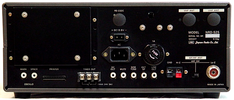
JRC NRD-525 Rear Panel
(no CMK-165 VHF-UHF Converter Installed)