![]()
SteppIR 3el Yagi from Fluidmotion
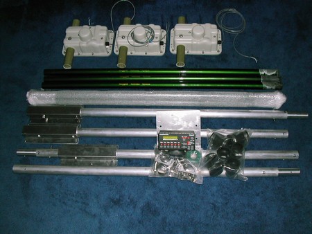
Complete antenna unpacked.
3 motorised control units for each element.
6 lengths of fibreglass tubes which extend to a minimum of 17' 8" each.
4 boom sections. A boom to mast plate and all the associated bolts and washes.
A set of 6 "quick-release" connectors. Enclosure and connector for element wiring system.
1 antenna controller and power supply for the shack end.
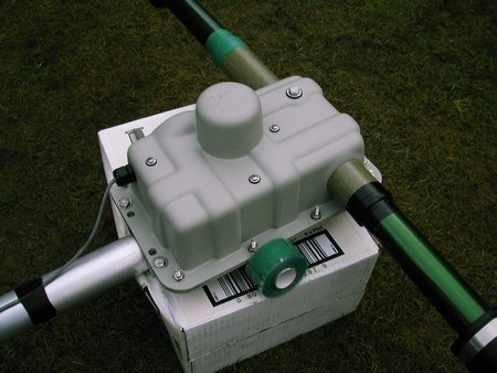
Picture shows one of the Stepp motors bolted to the boom.
The fibreglass is plugged into receptacles and secured with both electrical tape and silicon tape.
Though this is sufficient, I opted for the additional "quick-release" system for extra insurance!
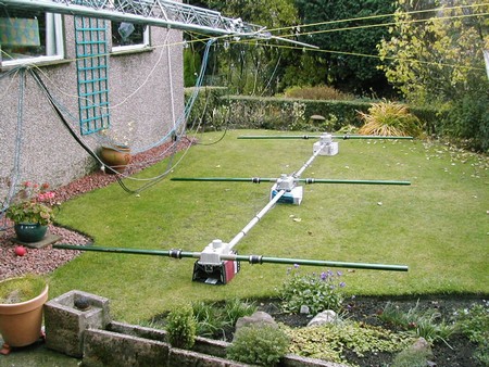
Almost done!
I have a small garden so the elements were not extended until the antenna was mounted on the mast.
Just the quick release boots to fit. The cables all went on last
.
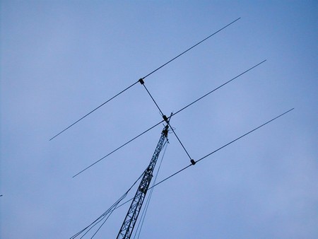
It's up and looking good!
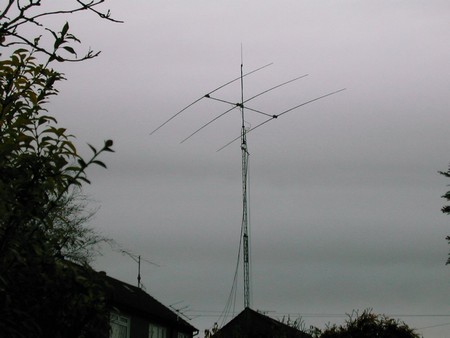
The 3el SteppIR is mounted on a 20' pole on top of a 60' Versatower.
A 2m vertical currently sits at the top though a 2m yagi will eventually be mounted below it.
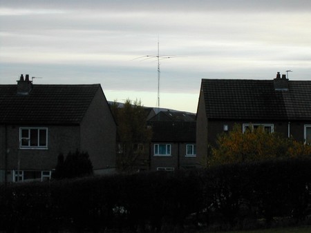
The neighbours view!
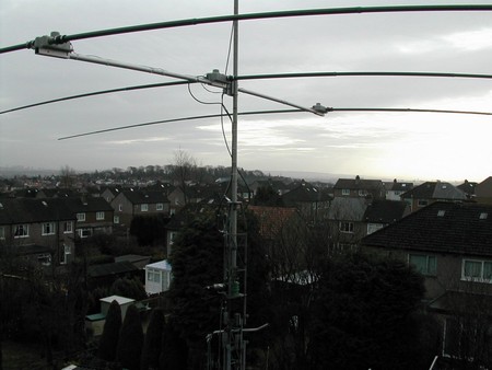
View from my shack with the tower right down.
I recommend the Prosistel rotator!
Overview
The requirements for a HF antenna rested upon my
numerous DX, Contest and ragchewing interests.
I do not have a large amount of land available
but I wanted optimum performance on as many HF bands as possible. I benefit
from having a 60' telescopic tower but only enough room for one!
Having had experience of using numerous
multi-band and mono-band beams over many years, I very neally went the route of
a log periodic to get good results over the range of 10m through to 20m.
I was giving some points away one weekend
during the SEANET Contest and one signal from
On checking their website I established they
were using a 3el SteppIR beam.
This was a new antenna to me so I decided some
investigation was required.
Here was a 3el beam that could provide
computer optimized results on all frequencies between 14Mhz and 50Mhz!
Fibreglass elements in which a berilium copper
strip transversed and is instructed on commands from rig control signals or
manually through a shack based controller. The ability to reverse the beam
heading or change bands within a few seconds electronically was an additional
bonus.
The European supplier is Ron GW3YDX of Vine
Antennas.
An order was submitted and it arrived within two
months.
The antenna came very well packed and no missing
parts. A good start!
Construction
The antenna went together with ease. Though I
started "by the manual", the size of my garden
caused a change in method. I found it easiest to
mount the boom to the mast first. Thereafter the
three SteppIR motors were bolted onto the boom.
The 6 fibreglass elements had been secured to
the motors and tape placed over the end of the
first section to stop the inner tubes coming out.
Each motor has a screened 4 core control cable
and these were tie-wrapped to the boom.
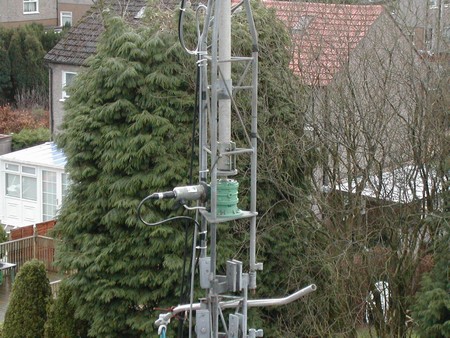
The antenna is linked to the shack based
controller via a length of screened 12 core cable.
The 12 core cable is inserted into one side of
an electrical contact strip, the 3 lots of 4 core cable
go into the opposite side. A separate connector
is used to insert all 4 remaining screening wires.
Anti-moisture compound is inserted into the
electrical block. A tie-wrap was used to support the
4 cables against the electrical block before
inserting it all into a capped tube which is anchored to
the boom to mast clamp. The last job was to
withdraw each fibreglass section of each element.
Silicon tape is used at each joint to stop
movement. Care must be taken to make sure each section
is pulled out fully so that the minimum length
of each element is 17' 8" or damage could occur when
the motors push out the Beryllium copper element
its maximum length.
The mast was raised and it was time to give it
an airing.
The shack controller is easy to operate.
The 12 core cable is connected to a 25 pin
socket on the rear. Other sockets are for data in which is
used for the optional transceiver interface. A
data out socket is present but not used at this time.
There are 2 dc power input sockets and the
antenna comes with one 24v 2.7A universal supply.
The only time both sockets would be used is if
there were 4 or more elements.
The front of the control has 6 band buttons,
20m, 17m, 15m, 12m, 10m and 6m.
There are numerous default settings on each band
with the exception of 12m and 17m with 1 each.
For example, pressing 20m can default to 14.050,
pressing 20m again takes it to 14.200 and again
puts the antenna on 14.300. There are "Up
and Down" buttons to enable manual fine tuning of 25Kc points within each
band except 10m (50Kcs) and 6m (100Kcs).
A unique feature is the ability to switch 180
degrees or beam bi-directionally. One button is used for
this feature. Each time you press the button an
LED displays what function you are using.
A mode and select button is used to go into a
menu system. This can enable you to move from the
default "Amateur" setting to general
coverage. Menus are also available for adjusting the factory
default frequency settings, selecting
transceiver setup, creating your own antenna, calibrating the
antenna or "homeing" the elements back
into the motors.
The optional transceiver interface negates
the need for the continual use of the shack controller.
The controller is connected directly to your
transceiver and the frequency of your transceiver determines the tuning of your
antenna.
On the Air (updated
Results have been beyond my expectations
running 100w with a TS940.
DX pile-ups I have joined in resulted in a
contact after only one or a few calls.
Some of the DX stations worked have broken with
their pile-up and wanted to chat.
I read results like this from other users but
hearing is believing!
The first weekend I spent some time giving
away points in the WAE RTTY Contest.
This antenna is absolutely superb for
contesting. It produced almost constant pile-ups and it was great
to keep the frequency clear and keep the qso pot
boiling by quickly being able to reverse directions or
direct power in 2 directions at the same time.
For general use and without cluster assistance,
I find listening around with the bi-directional mode is most
profitable. On hearing someone I want to call I
just switch to the forward or 180 degree mode depending
where the rotator is heading. No more waiting
for the "beam to come around".
I have carried out a lot of front, rear and
bi-directional checks on all HF bands and the results have
been most impressive. As we draw closer to the
sunspot minima, HF operators require greater awareness about the different
paths open to DX. This antenna allows such checks to be made very quickly.
Of course, with the bi-directional mode, you can
beam long and short path at the same time and then go directional on the reply
you go back to!
One "local" check. That was with
Jimmy GM3CIX who is about 10 miles away. He found
me S5 off the back and 9+10db off the front. I
need to do more checks but I am delighted so far!
Some DX stations like to take a fair chunk of
the band when operating split frequency and it can be
difficult to find where they are listening and
whether they are tuning up or down. The ability
to switch to 180 degrees or bi-directional
certainly helps in finding the station they are working in order
to call after a qso has been completed.
Switching directions takes around 3 seconds and can
save you minutes or even the chance of a contact
if conditions are changing to favour another area.
Anyone with experience of shunt feeding a
tower for 160m or 80m will be aware that a beam on top
of the tower acts as a capacity hat. I have read
of another 3el SteppIR user who has found an extra
bonus of his antenna in so far as any tuning to
different bands on the SteppIR enables him to tune his
shunt fed 160m antenna to different frequencies
on top band. Logical, but very useful!
More information, pictures and feedback are
available on FluidMotions website www.steppir.com
or for
What do I mean by frequency optimisation?
Well the antenna self or manually adjusts to the following
dimensions in inches. Try doing this with a
normal antenna! These are the measurements for only
200 kilohertz of the 20 metre band. For clarity
I have not included the dimensions for 180 degree or
bi-directional use and not all frequencies
between 13.600 Mhz and 54 Mhz.
|
FREQUENCY |
DIRECTOR |
DRIVEN ELEMENT |
REFLECTOR |
|
14.000 |
384.9 |
399.6 |
421.4 |
|
14.025 |
384.2 |
398.9 |
420.7 |
|
14.050 |
383.5 |
398.2 |
419.9 |
|
14.075 |
382.7 |
397.4 |
419.2 |
|
14.100 |
382.0 |
396.7 |
418.5 |
|
14.125 |
380.5 |
395.2 |
417.0 |
|
14.150 |
381.3 |
395.9 |
417.7 |
|
14.175 |
379.8 |
394.5 |
416.3 |
|
14.200 |
379,0 |
393.6 |
415.4 |
73 and come back for more feedback once I have had more chance to use the antenna.
Ray GM4CXM
|
|
|||