| ADVANCED LESSON 38 |  |
| LEARNING OBJECTIVES and NOTES | |
| Power Amplifiers | |
|
4g.1 Understand the need for linear amplification and identify which forms of modulation require a linear amplifier. In a linear amplifier the output is an exact copy of the input but with an increased amplitude. Certain types of modulation have to have a linear amplifier: SSB, DSB supressed carrier and AM produced by unbalancing the balanced modulator in an SSB transceiver. These would use a class A or AB amplifier These types of mode do not need a linear amplifier: FM, CW, or RTTY. A class C amplifier is used which is more efficient. See lesson 33 for different modes of amplifier. |
|
|
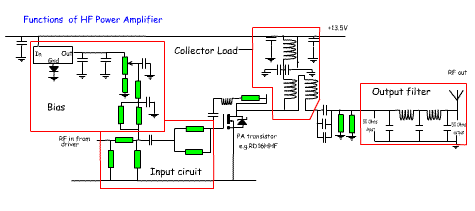
4g.2 Recall the function of the main components; anode/collector load,
bias, input circuit, output filter and matching in a PA circuit. The key parts are boxed in red. The drawing below shows a diagram of a typical RF amplifier. Do not learn the circuit, but concentrate on the key parts and what they do. This actually uses a Power MOSFET which is very popular for modern PA stages, either in push pull or single ended. |
|
 |
|
| The collector load (drain in a FET) This consists of a transformer and choke that ensure the desired band / range of bands is passed on to the output filters, and that the output impedance is 50 ohms. A set of 3 capacitors in parallel separate the collector from the filter at DC. These will handle a higher voltage and current than a single capacitor. Bias The transistors are biased using a voltage regulator. The actual bias is adjusted using the variable resistor. For class A (linear) amplification the bias is set to about 300mA This is suitable for SSB and AM. For class C for CW and FM the bias is set to about 30mA. A switch can be provided to enable the amplifier to be switched between the two. NB on the diagram the connection of the bias should be connected after the capacitor from the driver stage. |
Input circuit
Over driving an amplifier will cause distortion on the output. If the
input source has a higher power than required, then the first part of
the input circuit is an attenuator consisting of 3 resistors. A 6dB
attenuator would reduce a 2Watt signal to 500mA. The resistors will
need to be selected to dissipate the 1.5 watts of heat
Output filtering The output from the transistor will be rich in harmonics. So for a one band transmitter, a low pass filter is required that passes the required frequency, but cuts off before the first and subsequent harmonic. Again values of capacitors will need to be selected to withstand the higher voltages at the output of a transmitter. The low pass filter is designed for a 50ohm input and output. Matching The input and output impedances of the MOSFET will not be 50 ohms. The resistor network at the gate of the MOSFET will be selected to make the input look like the MOSFET input impedance. A transformer could also be used. The output load has to carry out the same impedance matching into the 50 ohm filter. |