| ADVANCED LESSON 39 |  |
| LEARNING OBJECTIVES and NOTES | |
| Power Amplifiers 2 | |
|
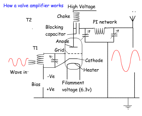
4g.3 Recall the operation of a valve in a power amplifier. Recall the function for the heater, cathode, control grid and anode. Recall the advantages and disadvantages of valve PA circuits. Although valves have almost disappeared from amateur equipment, they are still used extensively in high power linear amplifiers. How a triode valve amplifier works The filament heats up the cathode when the 6.3v is applied. As the cathode surface is warmed up by the heater the cathode surface produces a cloud of electrons. These are attracted to the positive anode. An impedance step up transformer (T1) which matches the 50 ohm input from the driver stage to the high impedance at the grid. The input wave is applied between the cathode and the grid. When the wave is going positive, some of the electrons are attracted to the grid and the anode current falls. When the wave is going negative, electrons will be repelled from the grid and more electrons will flow towards the anode. This variation in electron /current flow will follow the input wave and will cause an alternating voltage on the output side of the blocking capacitor. The Pi network acts as a low pass filter to reduce harmonics above the operating frequency. It also matches the high impedance output from the anode to the 50 ohms of the antenna. The two variable capacitors of the Pi network are labelled LOAD and TUNE on a valve linear amplifier. The coil of the Pi network is often switched to enable it to cover all the HF amateur bands. Often labelled BANDS. By adjusting the negative bias on the control grid different classes of amplifier can be implemented. For linear amplification (SSB and AM) the bias is set up for class A amplification. It is about 30% efficient. For class B the bias is set to only amplify part of the wave. These are about 50% efficient, but not as linear For class C amplification FM and CW the bias is set so that even less of the wave is amplified. These are about 75% efficient. Advantages and disadvantages of valve PAs Advantages * Very linear. Low distortion with no feedback required. * Have a high input impedance * Valves are high voltage devices and therefore can handle the high voltages in a linear amplifier. Transistors are low voltage devices and easily damaged by high voltages. * Very resistant to overloads * They plug into a base and can easily be replaced. * A single valve provides more gain than a single transistor and so fewer stages of amplification are required. If the antenna is resonant they are faster to start up than a valve amplifier. Disadvantages * Not as cost effective as transistors. Cost more to buy and replace * Need replacing more often * Need a separate heater supply that doesn't contribute power to the RF output. Take longer to set up requiring the adjustment of the BAND switch, LOAD and TUNE capacitors. * They create more heat that can affect the stability of nearby VFOs * Need to warm up before they will operate. This is overcome by leaving the heater permanently on (Standby). Transistors can be used immediately. * Need forced air cooling to keep them at a reasonable temperature * Higher voltages make circuits more dangerous to humans. * Valves all have the same polarity unlike transistors that have PNP and NPN configurations which make possible more circuit configurations. |
  |
4g.4 Understand the implications for PA rating of different types of modulation and the effects of speech processing, with particular regard to peak to average power ratios. By adjusting the negative bias on the control grid different classes of amplifier can be implemented. For linear amplification (SSB and AM) the bias is set up for class A or AB amplification. It is about 30% efficient. For class B the bias is set to only amplify part of the wave. These are about 50% efficient, but not as linear For class C amplification FM and CW the bias is set so that even less of the wave is amplified. These are about 75% efficient. It is assumed that linear amplifiers will be used for SSB mainly. If you look at a sine wave you will notice that the average power level is well below the peak power level. When the amplifier is used with speech processing or data modes such as RTTY or SSTV the average power is much higher and therefore the valve draws more average current. This puts a greater strain on the valve. It is a good idea to reduce the output in these modes to reduce the average power. This will lengthen the life of the valve. |
|
|
4g.5 Recall the function of automatic level control within the power
amplifier and when using an external power amplifier. Recall the
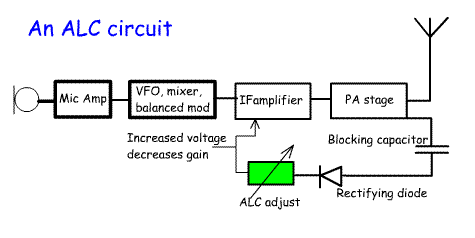
function and use of a manual RF power control. Most transceivers use an automatic level control (ALC) to control the output from the final amplifier stage..This is achieved by sensing the power via a capacitor, converting it to a DC voltage using a diode or a diode ring and feeding it back to an earlier IF stage which reduces the gain when the ALC exceeds it upper limit which is set by a variable resistor. External linear amplifiers often have their own built in ALCs to reduce the power to a predetermined level. Most transceivers also have a manual gain control. This can be used to set the power level between about 5 Watts and 100 Watts. This is used for example:
|
 |