
| ADVANCED LESSON 37 | |
| LEARNING OBJECTIVES and NOTES | |
|
Modulation If you tune into a pure carrier all the information you get is that a transmitter is transmitting. To add meaning to the carrier it has to be changed in some way. This is called modulation. |
|
|
4f.1 Recall the meaning of the term peak deviation. You will remember from the Intermediate exam that an FM transmission modulates the information by changing the frequency of the carrier. The peak deviation is the difference between the maximum carrier frequency and the unmodulated carrier frequency. For example the maximum carrier of an FM transmitter could be 145.505 and the unmodulated carrier 145.500. The peak deviation would = 145.505-145.000 = 5kHz. Or it is half the difference between the lowest frequency and the highest frequency transmitted. The less deviation, the smaller channel spacing required. For example: 5kHz peak deviation would be used for 25kHz spacing. 2.25kHz peak deviation would be used for 12.5 kHz spacing. |
|
|
Recall the meanings of wide band and narrow band frequency modulation. From an amateurs point of view wide band FM would be 5kHz peak deviation and 2.5 kHz peak deviation would be used for narrow band FM. So, narrow band FM will have a smaller peak deviation than wideband FM. This assumes no speech is applied. When speech is added the signal becomes wider. One of the formula given on the formula sheet is:  Where bw = bandwidth AFmax = maximum audio modulating frequency Delta f = carrier peak deviation frequency This is called Carson's bandwidth Rule |
Example 1 |
|
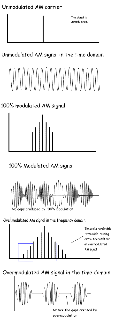
Recall the meaning of depth of modulation for amplitude modulation. In amplitude modulation, the height (amplitude) of the wave is changed by the audio modulating the signal. With no modulation, the RF waves have a constant flat top with 100% modulation, the RF waves follow the AF modulation. There are no gaps in RF where it meets the x-axis. This is the optimum. NB a 100% modulated AM signal produces peak power four times that of the unmodulated carrier.If too much audio is applied to the RF carrier, there are gaps in the RF. This will produce audio distortion in the AM signal. |
 |
|
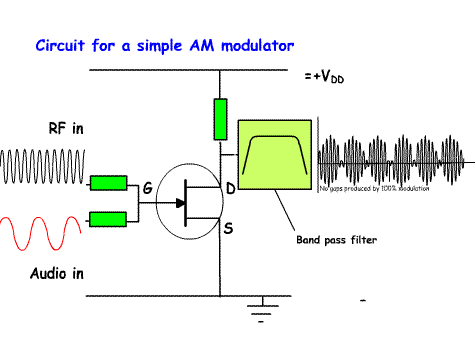
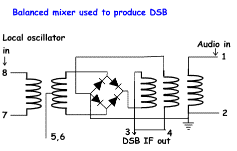
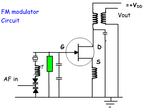
4f.2 Understand the operation of AM, SSB and FM modulators. Recall the bandwidth of such transmissions. Intermediate lesson 13 shows block diagrams of AM, SSB and FM transmitters. You would be advised to go back and learn these. This section shows circuit diagrams of the modulators for these modes. There is no need to learn the circuits, but concentrate on the key principles. AM modulator Here is a circuit of a simplified AM modulator using a FET transistor. The RF from the VFO and audio from the microphone amplifier are fed through resistors onto the gate of the FET. This will act as a mixer producing a modulated carrier wave. Unwanted products are filtered out using a band pass filter. In this type of transmitter the power amplifier will consist of class A linear amplifier. Originally AM was produced in a class C power amplifier. The amplified audio was used to vary the voltage to the PA anode using an audio transformer.This required large expensive transformers. In modern transceivers AM is generated at a low level, for example by unbalancing the balanced mixer so that a carrier is produced along with the two sidebands. The SSb filter is bypassed. The signal is amplified by a class A amplifier. This does not need large transformers. SSB balanced modulator A balanced modulator is basically a mixer designed to accept an audio input from a microphone; RF from a VFO or crystal oscillator and an output that consists of two sidebands and a reduced carrier. Following the balanced modulator the double sideband signal is passed through a crystal filter that will remove one of the sidebands, leaving a single sideband signal. There are various types of balanced modulator. One is based on diodes as shown in the diagram opposite. These can be bought ready made in a small metal can or made from separate components. You do not need to learn the circuit, But you should understand that a balanced mixer in an SSB transmitter has an input for the Local oscillator, an input for audio and output of a double sideband signal. For example the local oscillator could be at 9MHz , when audio is added at 1kHz the output is 9,001 kHz and 8,999 kHz. The carrier is suppressed. The double sideband signal is then passed through a 9MHz filter filter to remove the unwanted sideband. leaving either the upper or lower sideband. FM modulator The drawing opposite shows a basic FM modulator. The changing voltage from the AF in causes the double varicap diode to shift the carrier oscillator from sided to side. I.e to produce frequency modulation. The output is fed to the next stage. Often this stage is also used as a frequency multiplier. Not only will the frequency be multiplied, but also the deviation. So, if the output is five times the input frequency and we want a 5kHz deviation, then the varicap diode would need to deviate the frequency by 1kHz to produce a 5kHz deviation at V out. |
   |
| 4f.3 Understand, in functional terms, the operation of data modulators
for F1B (direct frequency shift), F2B (frequency shift keyed audio tone
on an f.m. transmitter) and J2B (frequency shift keyed audio tone on an
s.s.b. transmitter). Over the years amateurs have come up with their own abbreviations for different types of modulation. CW for Morse code, SSB for single sideband and FM for frequency modulation. The International Telecommunication Union uses an internationally agreed system for classifying radio frequency signals. Each type of audio signal is classified according to its: bandwidth method of modulation type of modulating signal type of transmitted information. Method of modulation F is used for frequency modulation J is used for SSB A for amplitude modulation Types of modulating signals 1. One channel containing digital information, no subcarrier 2. One channel containing digital information, using a subcarrier Type of transmitted information A Aural telegraphy, intended to be decoded by ear, such as Morse code B data, intended to be decoded by machine (radioteletype and digital modes) Learn these F1B Direct frequency shift (Here the digital data from a computer produces a voltage that is applied to the varicap diode of a VFO. This causes the carrier to move in frequency when the voltage changes. There is no need to have audio frequency subcarriers. This is also called FSK (Frequency Shift Keying) F2B (frequency shift keyed audio tone on an f.m. transmitter) Here audio subcarriers are produced which frequency shift the carrier) (This is also called AFSK (Audio Frequency Shift Keying) J2B (frequency shift keyed audio tone on an s.s.b. transmitter) Here the data output consists of a number of audio tones which are applied to the balanced modulator of an SSB transmitter. For example in RTTY there are two tones used - 1.275kHz and 1.445kHz. On a 14800kHz USB transmission these will appear as two frequencies of 14800 +1.275 =14801.275kHz and 14800+1.445 = 14801.445kHz. |