| ADVANCED LESSON 13 |  |
| LEARNING OBJECTIVES and NOTES |
|
||||||||||||||||||||||||
| Large and Small Units |
|||||||||||||||||||||||||
| Understand unit prefixes used to denote the size of a unit. NB Units will be used in multiples of 103 in any questions or calculations. The units we use in electronics are SI units. This means System International. All scientists have agreed to use these units. The key units used in the technical side of radio are frequently too large or too small to be used in calculations. For example when measuring the diameter of a piece of copper wire, the meter would be too large. We are more likely to use the millimeter (mm) or even the micrometer (um). When measuring frequency in Hertz it is often too small and so we use the kilohertz, megahertz or even the gigahertz. Opposite is a table of prefixes used.Units of capacitance (Farads) are used as an example. |
|
||||||||||||||||||||||||
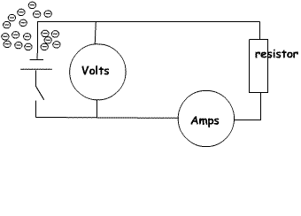
| Voltage Understand the concept of voltage and current, Potential Difference and Electromotive Force Voltage is the measure of the difference between the number of electrons at two points in a circuit. Current is a measure of the number of electrons flowing through a wire or component. In this simple drawing of a circuit when the switch is open electrons (shown as a cloud of - symbols) cannot flow and so there is no reading on the meters. When the switch is closed, electrons will flow through the resistor and ammeter which will show a reading of the electron flow (the current). A small number of electrons will flow through the voltmeter showing the voltage difference between its two terminals. So, current is a measure of electron flow and voltage is a measure of the difference in the number of electrons at two points. The potential difference. It is the potential difference in volts that causes the electrons to flow in the circuit. The two wires from a voltmeter are placed across a component. To use an ammeter a wire is cut and the two cut ends are connected to the ammeter. |
 |
||||||||||||||||||||||||
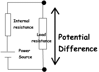
| 3a.1 Understand the difference between potential difference (p.d.) and electromotive force (e.m.f.). The Potential Difference is the difference between the voltage at any two points in a circuit. |
|
||||||||||||||||||||||||
Conventional current flow and electron flow.When the first circuits were built, the electron had not been discovered. It was decided that current would flow from positive to negative. When the electron was discovered it was found that electrons flow from negative to positive. But, it was too late to change the idea that current flows from positive to negative. So you have to remember that current flows from positive to negative and the arrows on diodes and transistors show this "conventional current" flow; but electrons flow from negative to positive.It is also important to remember that electrons do not move very far. They are very, very small, but once the switch in a circuit is switched on they will flow throughout the circuit. |
|||||||||||||||||||||||||
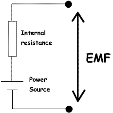
Understand the concept of source resistance (impedance) and voltage drop due to current flow.Potential DifferencePD is the voltage that appears at the terminals of a power source when a circuit is connected which causes current to flowElectromotive Force (EMF) EMF is the voltage that appears at the terminals of a power source when no current is flowing. |
  |
||||||||||||||||||||||||
|
Difference between source resistance (impedance) and voltage drop due to current flow All power sources have some resistance. On circuits this is often shown as a resistor as shown in the drawings above as "Internal Resistance". When a circuit is completed, for example when a circuit is switched on there will be a voltage drop across the power source. For example a PP3 battery has a high source resistance. This can be useful as it will reduce current flow. A car battery has to be able to deliver many amps at start up, therefore it has a very low internal resistance to allow the high current to flow. |