
| ADVANCED LESSON 24 | |
| LEARNING OBJECTIVE and NOTES | |
| Transformers | |
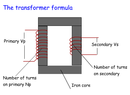
| 3j.1 Understand the concept of mutual inductance. Understand and apply the formulae relating transformer primary and secondary turns to primary and secondary potential differences and currents. A transformer is used to raise or lower the voltage of an AC sine wave. For example most modern transceivers have a power supply that converts 240V mains to about 12V. How a transformer works: A number of turns of wire are wound on a core of iron or ferrite. Another coil is wound on the same core, but with fewer turns. When an alternating voltage is applied to the first coil a lower voltage appears at the output of the second coil. This transfer of energy from one core to the other is called MUTUAL INDUCTANCE. This will take place without the core, but the core improves the transfer of energy. In the same way that a voltage can be stepped down, it can also be stepped up by having a secondary coil with more turns than the primary core. The actual transformation from one voltage to another can be calculated using the following formula: 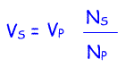 Where Vs = voltage on secondary Vp = voltage on primary Ns =number of turns on the secondary Np =number of turns on the primary The actual transformation from a maximum current that can be drawn can be calculated using the following formula: 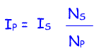 Where Is = current in secondary Ip = current in primary Ns =number of turns on the secondary Np =number of turns on the primary From Example 2 we can see that in a step up transformer the current available from the secondary decreases. In a step down transformer the current from the secondary increases. |
 Example 1 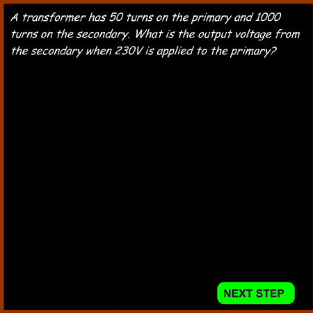 Example 2 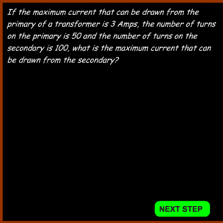 |
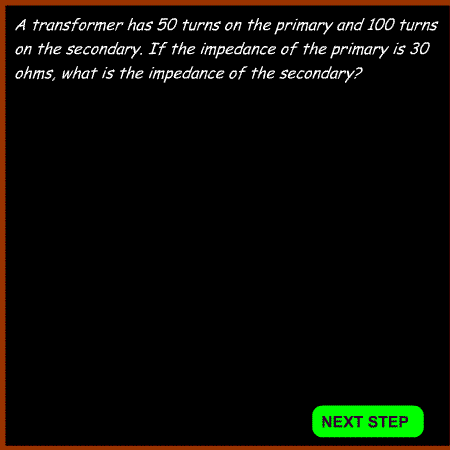
| 3j.2 Understand and apply the formula relating transformer primary and secondary turns to primary and secondary impedances. As we are dealing with AC, the transformer primary and secondary will also have specific impedances. This is important when we are dealing with RF transformers as we often need to transform one impedance to another. For example most inputs to transceivers have a 50 ohm impedance, so the primary coil linked to the antenna will need an impedance of 50 ohm. If this is feeding into an RF amplifier with an impedance of 500 ohms, then the output will need to have a 500 ohm impedance. This is the formula for calculating impedances in transformers: 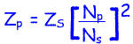 Where Zp = impedance of primary coil Zs = impedance of secondary coil Np = number of turns on primary Ns = number of turns on secondary |
Example 3
 |
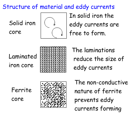
| 3j.3 Understand the cause and effects of eddy currents and the need for laminations (or ferrites) in transformers. As we have seen above, a core of iron is used to improve mutual inductance in transformers. Not only does the primary field induce a current to flow in the secondary winding, but it also causes Eddy currents to flow in the core. This produces a loss of energy in the secondary winding and causes the core to increase in temperature. For eddy currents to flow there has to be a circuit. By breaking up the core with some sort of insulation these circuits cannot form and so eddy currents are reduced. In iron cores this is achieved by using slim sheets of iron (laminations) separated by insulation. This prevents eddy currents circuits forming. However it is only effective at low frequencies such as the 50Hz of the mains electricity supply. Ferrite cores are non conducting - try measuring the resistance of a core with a resistance meter. This means that eddy currents can not form because of the high resistance of ferrite. These can be used as the core of transformers at much higher frequencies. |
 |