
| ADVANCED LESSON 25 | |
| LEARNING OBJECTIVES and NOTES | |
| Filters | |
| 3k.1
Identify the circuits of low pass, high pass, band pass and band stop
(notch) filters and their response curves. Understand the concept of
the cut-off frequency. On the Intermediate paper you were asked to learn the shape of different types of RF filter. These are shown opposite as a reminder.On the Advanced paper you will be asked about the circuit diagrams used to create these filters. Here are some key points about filters: All of these filters are based on different combinations of inductors and capacitors. Each inductor or capacitor is called an element. The more elements in a filter, the better the response curve, but the greater the losses. These are all 5 or 6 element filters. Filters are designed for a specific input and output impedance - usually 50 Ohms in amateur radio RF filters. Filters can start with either inductors or capacitors. Filter design is much easier nowadays using a computer program such as Elsie In the low pass filter the signal has to first pass through an inductor. In a high pass filter the signal has to first pass through a capacitor. In a band pass filter the signal has to pass through an inductor and capacitor in series, a parallel resonant circuit is placed before and after the series circuit to ground. In a band stop or notch filter the series LC parts of the circuit are connected to ground before and after a parallel LC circuit. You need to learn these four arrangements. The majority of band filters are used after the antenna input to a receiver. A common arrangement in an all band transceiver is to have filters covering 0-2MHz; 2-4MHz; 4-8MHz; 8-16 MHz and 16-32MHz. They are switched by diodes, IC switches or relays. A bank of low pass filters are used between the PA stage and the antenna to remove unwanted harmonics. A notch filter may be used at the front end to remove any signals on the IF frequency. |
  |
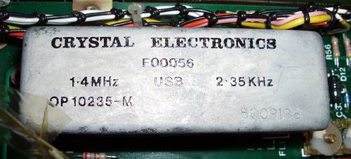
| Recall that crystals can be used in filter circuits. In many HF transceivers a filter made of crystals is used to filter out the IF signal. These are narrow (2.4kHz to 500Hz), they are very stable and take up less room than an equivalent circuit made of capacitors and inductors. In the transmit path they can filter out one sideband from a double sideband signal. A typical arrangement would be to have a 2.4kHz crystal filter for SSB and a 500Hz filter for CW. For home brewers a common design used is the ladder filter. This consists of a series crystals with capacitors to earth. Computer programs can be used to calculate the value of the capacitors. The crystals are all the same value and often bought in bulk. The more crystals, the narrower the bandwidth. |
  |
| Screening |
|
| 3l.1
Recall that screening with thin metal sheet is effective in reducing
unwanted radiation from equipment and/or between stages within
equipment. To prevent signals from one part of a circuit being picked up by another part of a circuit it is common to use screening. This consists of small sheets of thin tin plate soldered to the ground plane of the circuit board. Double sided copper board may also be used. When RF encounters the screen the signal is conducted to earth. Fully screening a particular stage can also prevent unwanted radiation of RF from the radio. If you look inside a radio common areas for screening are oscillators, synthesisers and RF amplifiers. Screening can also prevent stages such as the IF stage picking up RF on the intermediate frequencies. Most radios are built into metal enclosures to provide screening for all the stages. |
 This
image is a radio tuner. The circuit is encased in tin-plate to
prevent radiation from the oscillators and pick up of RF.
|