Heathkit SB Line -
This page considers the problems that have occurred over many years and what improvements could be made to the popular SB-
1. There are a number well documented problems, a lot due to age:
a) Electronics: Carbon composition resistors age high in value of many years and it is not unusual to see values of several times their original -
b) Active devices: 6146 PA valves do eventually go soft and/or exhibit low emission -
c) Mechanical: The lubricant on the LMO tuning capacitor moving contacts and overturn mechanism dries out and needs replacing, the paint on the cabinet flakes off, the metal on the control knobs gradually tarnishes, the valve holders lose their tension and contact become intermittent, the PC board to chassis mountings develop high resistance affecting the performance. The SB101/HW101 relays develop contact issues and degradation of the internal insulating surfaces due to splatter from the contacts during arcing.
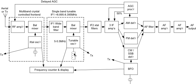
d) Performance Issues: The bands are much busier and more congested than in the 1960s/70s and this results in performance problems when the bands are open and busy or contests are in progress, particularly in Europe. The original architecture has insufficient gain in the second IF and too much RF gain increasing the intermodulation products, the mixers are not balanced, the AGC is not delayed to the RF stage limiting the signal to noise ratio, the crystal filters have insufficient stopband and adjacent channel attenuation, the receiver AM filters were too narrow for adequate quality and the tunable IF wide band filter has insufficient skirt attenuation.
e) Functional issues: It is unreasonable to compare functionality with modern equipments but there were a number of notable omissions that could have been addressed at the time: Top Band (1.8-
Some of these issues can be addressed through regular maintenance and cleaning work and there is at least one USA manufacturer providing replacement compatible electrolytic capacitors and another providing improved crystal filters.
2. So what could be done to improve the performance without major surgery? The use of PC board construction significantly limits the options. Crystal filters may be changed for improved models but these were supplied by International Radio, a company not related to Heathkit. Full break-
3. If you are prepared to do some major surgery then your options increase dramatically but this requires a lot of time and patience as well as technical expertise or a local Elmer:
a) Your first decision is to accept that the inflexible PC board construction can no longer used as it is just too difficult to modify. What I do is to fully disassemble the unit and remove most of the chassis top plate with a hacksaw leaving just a narrow amount of metal to form a lip, about ¼ to 3/8 inch wide all round the edges, on which a brand new aluminium chassis plate may be mounted. The original chassis plate may be used as a template to mark out mounting apertures and holes for the PA compartment, LMO, preselector etc.
b) The SB-
c) Mixers: By far the best balanced valve mixer is the 7360 beam deflection tube which are still available but now quite expensive. There are other types of beam deflection mixer like the 6AR8, 6JH8 or 6ME8 but while they are fine for transmitter applications they are not as good for receiver use. One alternative is to use a low noise dual triode balanced mixer like the 12AT7, ECC85 or ECC88. Using balanced mixers will increase the IF rejection and reduce spurious responses on both receive and transmit. My rebuild of an SB310 receiver to cover all the HF bands except 60m shows both IF rejections approaching 90dB.
d) Crystals: Crystals age and change in both frequency and activity so when they eventually reach their end of life they need to be replaced. Thankfully there are still some crystal manufacturers that will make one off crystals to order but not cheap.
e) Crystal Filters: Crystal filters are a more difficult topic as only a few early manufacturers used an IF of 3.395MHz. The original CW filter had four crystals, the SSB filter had six crystals which are both insufficient for current band conditions. One option would be to add two extra crystals to each filter by stripping down two additional filters and using some of the parts but the result would not fit into the original enclosures so this would require some design effort, new enclosures and extra construction work.
One possible option would be to use a slightly different frequency based on easily available high volume crystal frequencies. The nearest would be 3.2768MHz, approximately 118KHz lower in frequency which would require the VFO/LMO frequency range to be raised by the same amount. Eight pole ladder filters at this frequency would easily provide passband widths from 300Hz to 2.4KHz, 2:1 shape factors at -
f) Wide band RF filter: There is a design elsewhere on this website for a five pole 8.4 -
g) Audio Band Pass Filter: An audio filter is always useful to reduce the remaining noise on the post detector signals. A simple high pass and low pass arrangement is easy to design using active or passive circuits to reduce the signal levels below 300Hz and above 2.7KHz for speech applications and narrower for CW.
h) Automatic Gain Control: With careful design it is possible to combine good AGC control with fast muting for full break-
4. Transmitter Suggestions
a) Full break-
b) T/R Switch: On a transceiver or separate transmitter a classic cathode follower T/R switch may be constructed on the outside of the PA enclosure using a low noise high slope triode. I use this type on my modified SB401 transmitter. The advantage of this device is that it will use the impedance step-
5. VFO/LMO: These were generally good but do suffer from the lubricant on the variable capacitor and overturn mechanism drying out resulting in stiffness in the tuning shaft and irregular frequency jumping. The solution, easiest while your main unit is in parts, is to carefully remove the tuning capacitor, give it a good clean, wash the bearings, sliding contacts and overturn mechanism with a solvent cleaner or ultra-
When you have completed this work you will still be using ‘old’ technology but with a significantl increased performance. My rebuilt SB310 works well in HF CW contests and my modified SB-
6. Solid State Development
If your interests lie in the solid state arena then there are many ideas elsewhere on this site for the design / construction / modification of Heathkit equipment, for example the H-
Page under development….