IF Band Pass Filters
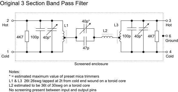
1. The SB101 and related designs used a tunable IF architecture with a crystal controlled front end converter to reach each amatuer band. The first IF of 8.395 to 8.895MHz used a three section band pass filter as shown below.
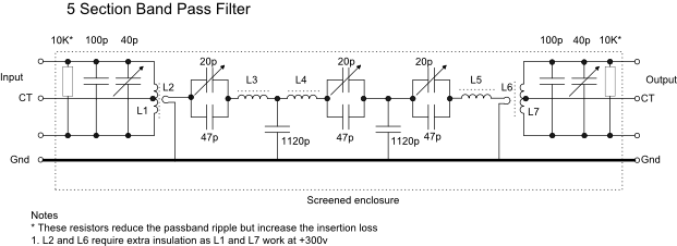
2. The following filter offers a narrower passband and increased stopband attenuation at the expense of a small increase in insertion loss compared to the filter above but this is not an issue as there is adequate gain in both the new transmit and receive paths. The balanced input and output transformers enable connections to beam deflection mixers 7360 on receive and 6AR8 mixers on transmit as well as transforming to and from the low impedance of the three central sections.
All inductors are wound on T50-
L1 and L7: 24t 0.5mm bifilar wound (balanced) or single winding for unbalanced mixers
L2 and L6: 2t 0.3mm, with sleeving, close wound over the centre of L1 and L7 respectively when bifilar wound or over the cold end when single windings.
L3, L4 and L5: 43t 0.3mm single layer
All wire is singe strand solderable enamelled copper
Frequency Response measured with an open PC board and without the 10K resistors:
|
Attenuation dB |
Low frequency edge MHz |
High frequency edge MHz |
|
- |
8.355 |
8.98 |
|
- |
8.251 |
9.092 |
|
- |
8.068 |
9.262 |
|
- |
7.716 |
9.61 |
|
- |
7.326 |
10.47 |
|
- |
6.953 |
N/A |
The -
The 10K resistors, when connected, increase the insertion loss from 6dB to 8dB and decrease the passband ripple from 3dB to 1.5dB.
This filter has been constructed on a double sided fibreglass PC board that is mounted inside a slimline die cast box. Each toroidal inductor has an insulator between it and the PC board surface. All trimmers are mica compression types, all fixed capacitors are silver mica 5% or better. Depending on the external circuit capacitances and the range of the trimmers, the 100pF fixed capacitors may need to be reduced in value by a small amount.
The width of the passband is controlled by the coupling factor between each filter section but no fine change is possible with the turns ratio of the transformers so the only options are the 1120pF capacitors. Reduce them to increase the width of the passband. 900pF results in 700KHz width and 680pF results in 800KHz width -
All inductors and their fixings have been varnished with clear polyurethane lacquer.
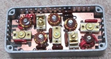
The picture to the right shows the completed filter in its four inch (102mm) long die cast box. The red sleeved link windings are clearly visible. The connecting leads will exit through grommet lined holes at each end of the removeable lid. Trimmers will also be accessible through insulated holes in the lid. The case will be mounted on the chassis using tapped holes in one end.
I have now made two of these filters with very similar results. One filter has balanced input and output for use with 7360 or similar mixers and one has unbalanced input and output for conventional Heathkit single ended (unbalanced) valve mixers.
If you have problems obtaining the mica trimmers try the next larger value -
The Q of the tuned circuits is high and tuning is quite sharp so the trimmer screws should be locked with beeswax or similar after alignment but not varnish which is too difficult to remove should retuning be required.
Access to the trimmers is via holes in the die cast box lid which have grommets fitted to prevent shorts between the trimming tool and the case. The input and output trimmers are at HT potential so much care is needed to prevent electric shocks.
Initial alignment was carried out with a Rigol Spectrum Analyser and Tracking Generator using temporary two turn link windings over L1 and L7. Final alignment will be carried out in circuit. If the final ripple is excessive in-
If you would prefer to use this filter with a solid state receiver or transceiver then you can provide taps or link windings on L1 and L7 to match your required impedance.