Valve Circuits 3
Full Break-
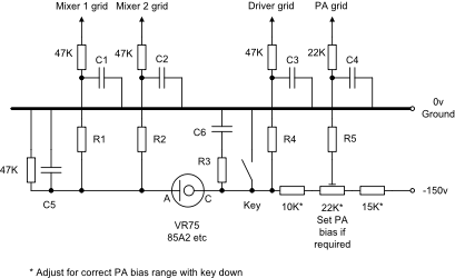
1. Grid Block Keying
The circuit to the right shows a very basic transmitter control using grid blocked keying for a typical dual conversion SSB/CW transmitter. In the key up condition the transmittor is prevented from generating any output. Note that all other stages must be capable of running without damage or over-
If the application uses one or two or three mixers in the transmit path then all of them must be keyed to prevent any by-
Envelope shaping to prevent key clicks, chirp etc is achieved using time constants R1/C1, R2/C2, R4/C3 and R5/C4 which should be selected for each individual application. Typical rise and fall times are around 2ms -
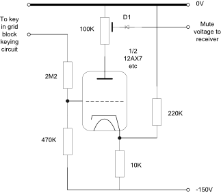
2. Receiver Mute
The following circuit generates a negative voltage used to mute the receiver when transmitting. Modifications to the AGC system will be required to enable the receive AGC time constant to be isolated from the muting facility. The values shown may need to be adjusted for each users particular circuit and operating voltages.
With the key up the triode should be cut-
3. Valve T/R Switch
The following circuit is a T/R switch that can be used with low and medium power PAs to isolate the receiver during transmit periods.
- The PA must be completely cut-
off on receive to ensure that any noise due to its anode current is fully suppressed. The above example break- in circuit achieves this requirement. - Cathode followers are not unconditionally stable so if any tendency to oscillation is noted then place a 22 ohm resistor in series with the feed to (and close to) the control grid.
- The cathode resistor may need to be adjusted to get the correct bias conditions for the particular valve in use. If the final value is significantly less than 470 ohms then a small RF choke may be required in series with the resistor to minimise losses of signal level.
- This T-
R switch has one slight disadvantage in that the Pi tank circuit provides a step- up in the received signal levels which can cause overload problems in the associated receiver - this can be corrected by using the receiver aerial attenuator switch or a capacitive attenuator feeding the TR switch control grid. - The circuit should be constructed adjacent to but outside of the screened PA compartment and all power lines well decoupled.
NOTE: This circuit is intended for use with a valve receiver which is more tolerant of RF voltages at the aerial socket than its solid-
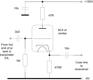
The 2p2 capacitor should be constructed from two 4p7 or three 6p8 capacitors in series to ensure a sufficiently high working voltage (at least three times the PA anode supply for reliable operation). Connect one end of this capacitor to the hot end of the pi-
If you are concerned about possible heater-
This circuit is in use in a modified Heathkit SB-
Extreme care is required when working on this type of equipment with the high voltages involved. Make sure that it is switched off, disconnected from the mains supply and the internal supply lines are all fully discharged before working on the equipment. If you are unsure then get qualified help.