Rhombic Antenna for 6m
Introduction
 The Verulam Amateur Radio Club (VARC) in St Albans annually holds an 'Antenna Shootout' where members put the minds to producing an aerial to a theme. Last year it was an 'Antenna In A Suitcase', the previous year it was an antenna for portable operation.
This year with the lockdown situation due to the Covid-19 epidemic and no-one able to meet, the shootout was based on producing a 6m aerial from bits that you have hanging around the home QTH.
Parts
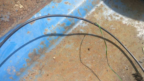
One thing I have fancied playing with for a long time is the Rhombic antenna. It has a very good directional gain and in principal is easy to construct. The problem is that on HF a Rhombic is extremely large. Even on 6m the antenna is pretty big! One thing I tend to hord is wire, and for this job I decided to get a length of old multi-core telephone cable that was salvaged from the side of the road when they changed the telephone cable up our lane! This cable consited of two pairs of wires which along with three individual red wires encased in a black plastic sleeve.
I used the two pairs of wires as that was the easy way to get them out of the sleeveing, as the pairs were wound about each other I had one length made up of the orange and white wire and another length made up of black and green wire.
It took a bit of effort to extract the wires, but at the end I had enough length to build the antenna and also have enough to make about 10m of balenced feeder.
Plans
The idea was to produce the antenna elements and the balenced feeder all in one length per side, so the two lengths of wire made up one side of the antenna and one side of the balenced feeder each.With a little research on the web it looked like the best bet was to mount the aerial at one wavelength above the ground - 6m, and for each side of the rhombic to be two wavelengths long (11.34m) and for the angles to be 60 degrees at the ends and 120 in the middle. This gave an overall length of 19.64 meters end to end and 11.34 meters from side to side.
Balenced Feeder
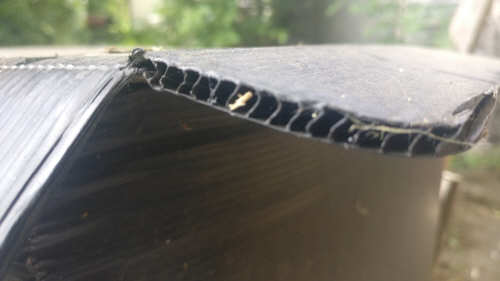 The main material to make the spacers for the balenced feeder came from the corrigated plastic that I found from an old motorbike back box - the type that you would see with pizza deliveries etc. They also use the same type of material in some 'For Sale' signs that you see outside houses.
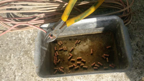 I cut a large number of pieces of mains wire into roughly 1cm pieces, these were to be used to wedge the wire of the balenced feeder in place in the corrigated plastic.
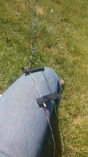 When you make a rhomic you have a choice as to whether to make it uni-directional, or bi-directional. To make it uni-directional (firing in one direction - givng the most gain) you need to put a 600 ohm load at the opposite end of the aerial to the feed point, but to make it bi-directional you leave the ends open.
Not having a 600 ohm load that could take 100 watts I decided to go for the bi-directional option!
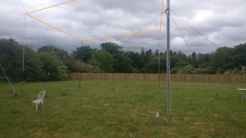
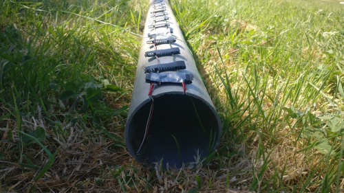
The support where the aerial is fed was made from 6 inch drain pipe with a couple of grooves sawn in the to to allow the aeral wires to move off at the right angle (60 degrees). The balenced feeder was taped to the side of the water pipe before it was lifted up into place
The angle of the antenna was such that it fired the signal at 340 degrees in one directiona and 160 degrees in the other. With that orientation I was firing my signal up the country towards Scotland and in the opposite direction through the middle of Europe.
The opposite end of the aerial to the feeder was held up with 4" downpipe and the sides were made with two extendable polyurethane pipes that came from stockwood ham rally one year. They weren't quite 6m long, so had to extend them by mounting them on a 4ft length 3/4" water pipe that I happen to have hanging around.
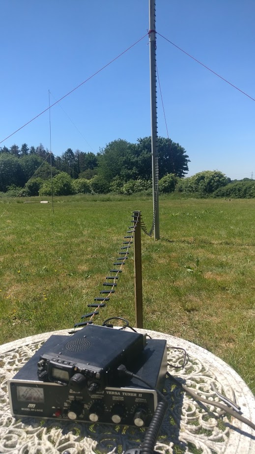 Wire antennas are not easy to photograph, so in the photo below I have marked where the aerial wire runs.
I made about 6 contacts into Italy and Spain during one sporadic E session, on one occasion getting an S9 +10db report from a Spanish station with my 5 watts from the FT-817.
I also run it during one of the 6m contests and was able to compare it with the Moxon that I usually use. Because it is set in one direction, most times the Moxon was giving be better results, but there were occasions where the rhombic gave me around 3db better readings than the Moxon. This is obviously because I can't rotate the rhombic and most likely the times I got the stronger signal from the rhombic was when the station in question was in the firing like of the rhombic.
So with that in mind I would say that the rhombic is an excellent antenna for point to point communications in one (or two) directions, but for 'normal' ham work it is not flexible enough.
Still it was a very interesting project and good fun to build!
73 Peter G0OIK.