This website relates to the recreational
pastime and hobby of Amateur Radio, promoting the science of
experimental radio communications & related technology,
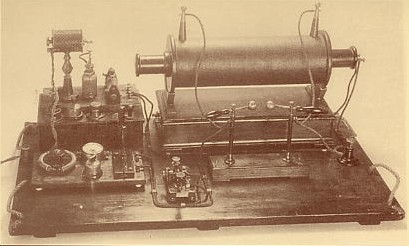
founded by the famous Guglielmo
Marconi in 1895. Exciting new discoveries relating to VHF radio propagation or
experimental new communication modes are
still being made in the 21st Century.
This website was originally
created on 1st September
2000, by
Philip G0ISW to
assist other Radio
Amateurs to experiment, research and achieve Very High Frequency (VHF) DX (long distance)
communications in the 50 MHz, 70 MHz and 144 MHz
bands, as well as being a useful operatingaid, having essential
propagation information on one page. Additionally the site has been designed not only for
licensed Radio Amateurs, but also for members of the
public who are not licensed to transmit, but who may have an interest in some
of the topics discussed or are aspiring to join the hobby.
If you cannot see the full
index shown on the left edge of your screen, please go to my main page athttp://www.qsl.net/g0isw
As a visitor to this website please, please
Sign my
Guest Book, as I spend a considerable amount of personal time maintaining this
site.
I really appreciate your positive comments, suggestions etc. Your
Guest Book entries greatly help to maintain my enthusiasm for continuing
this task after doing it for the past 26
years!
As a service to all Radio Amateurs,
the science and technology community and for the general public, this site was created by me on 1st
September 2000 and has been maintained and updated since,
voluntarily in my own spare time, for the benefit of all. It is also
intended to enhance Britain's reputation and to help generate new
scientific innovations.
The 'magic' with VHF signals
is that
Amateur Radio signals
in the frequency bands
50 MHz, 70 MHz and 144 MHz are predominantly 'line of sight',
typically short range with distances at ground level between
0-50 km and are blocked easily by obstacles such as hills or
buildings. If these signals are not obstructed and are sent from ground
transmitters into the air they will travel straight out into Space for
significantly greater distances.
Using experimental techniques and via 'enhanced propagation' it is possible to reflect these VHF signals
back to Earth from Meteor trails,
Auroras,
Sporadic-E,
Aircraft, Satellites
and even
the Moon
Sometimes, but rarely it is even
possible to extend the range of VHF signals to several thousands of km and even
reach all Continents, including Australia!
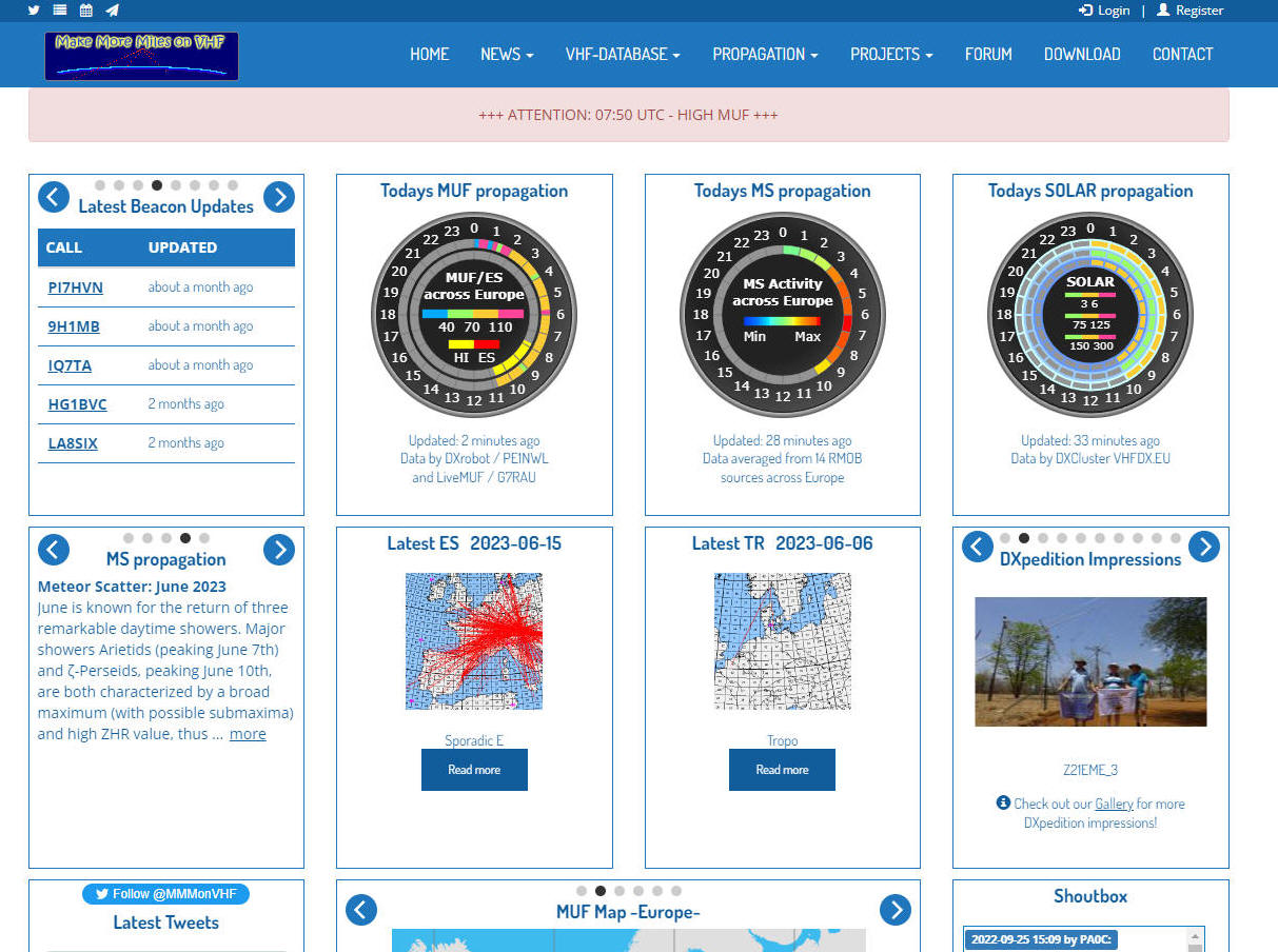
The section below is designed to be a single
page at-a-glance indicator of current VHF Propagation conditions,
particularly useful if just home from work or to monitor whilst in your shack.
Right click on images below
and select open link in new tab
TROPO DUCTING
SPORADIC ES
METEOR SCATTER
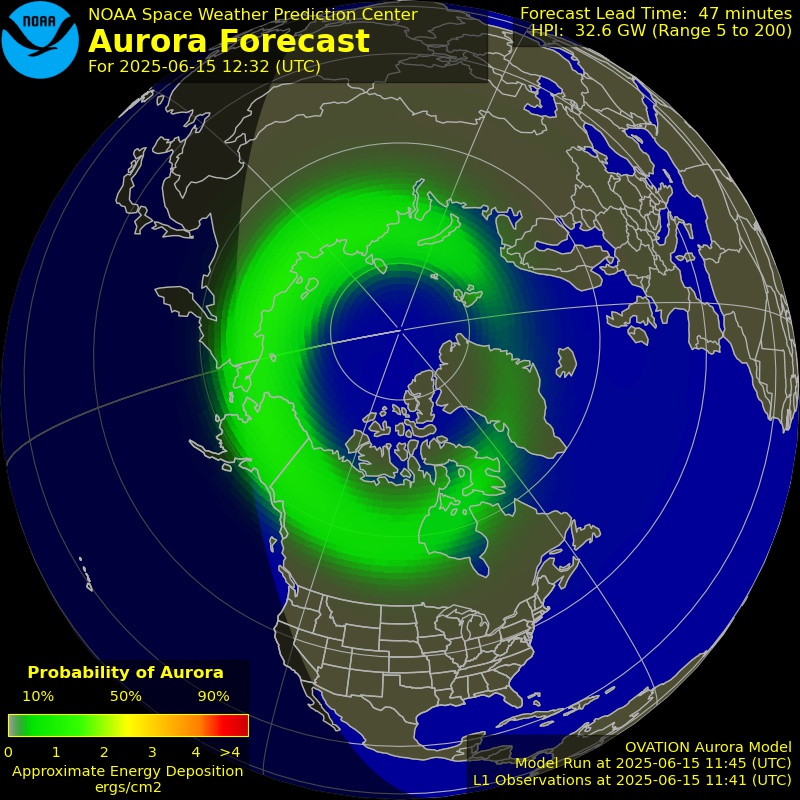
AURORA NOW
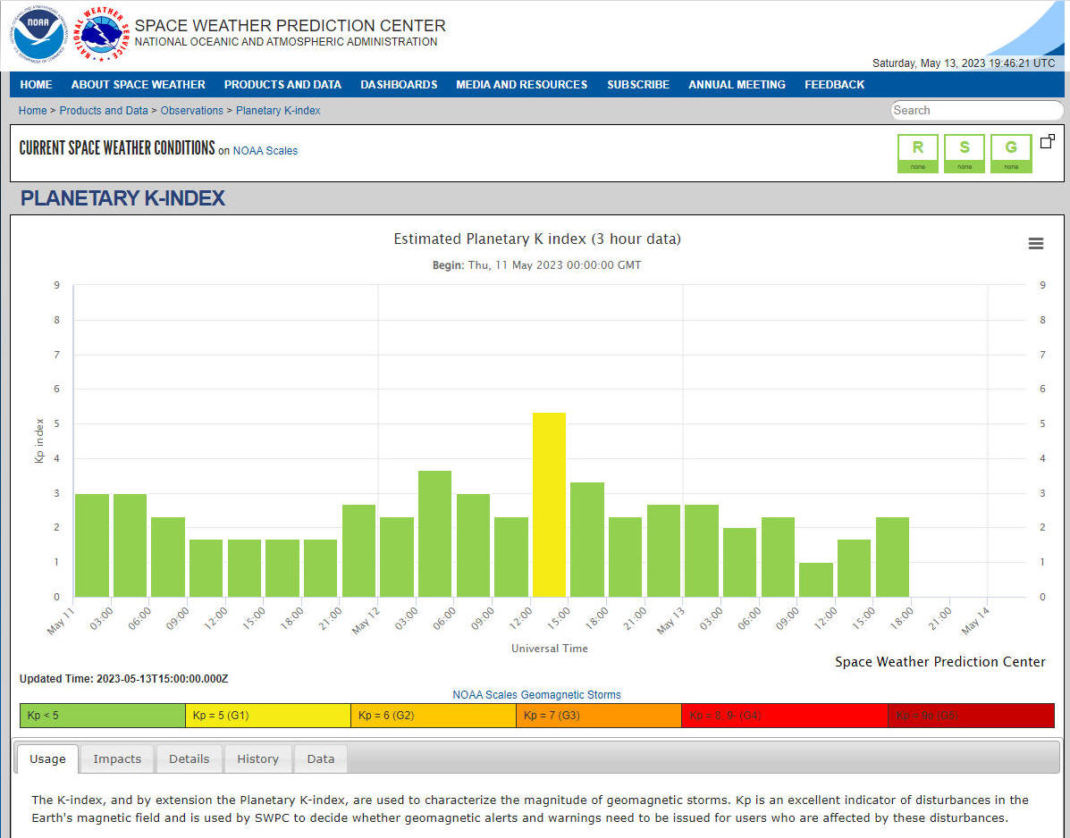
PLANETARY K-INDEX
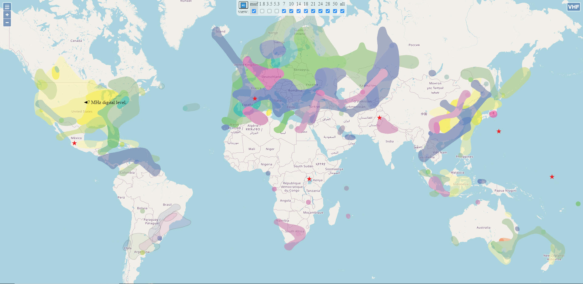
50 MHz PROPAGATION
MAP
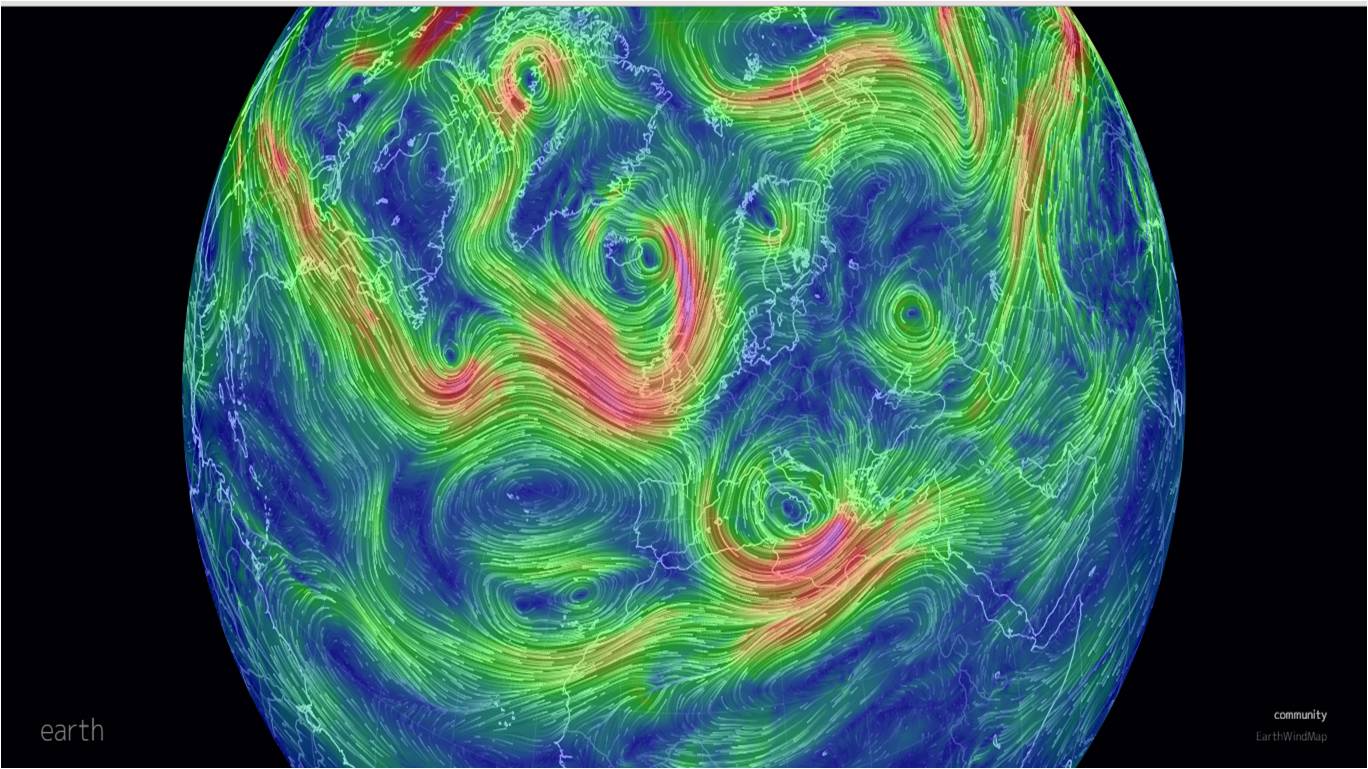
JET STREAM
144 MHz TROPO MAP
VHF DX CLUSTER MAP
UK AIR PRESSURE
CHART
FMLIST PROP MAP
MMMONVHF
TEC MAP EUROPE
PROPQUEST
HUXt FORECAST
AURORA TONIGHT
MAGNETIC FIELD
AURORA MAP
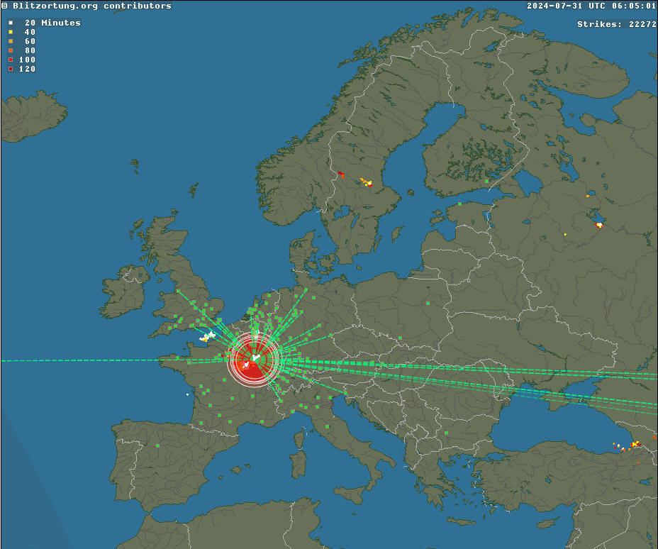
LIGHTNING MAP
ESTOFEX
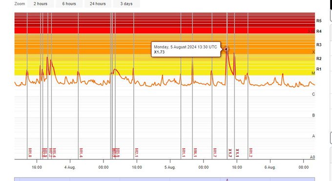
SOLAR FLARES
METEOR SHOWERS
JET STREAM
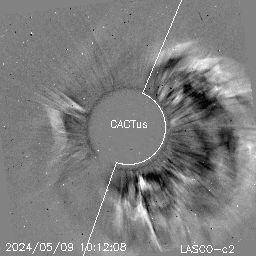
CME
VHF Propagation
Identification(V3.50)
June 2026
DISTANCE
<50-100km
100-400km
400-800km
800-2400km
2400-4800km
4800-7200km
7200-9600km
9600-14000km
Propagation type
Line of Sight (LOS)
Tropo Scatter
(TRS)
Tropo Ducting
(TRD)
TRD + Sporadic-Es (TRDES)
Aurora (AU)
Auroral-E (AUE)
Sporadic-Es
(ES) very rare at short 400-800km distance
(50-90
MHz not 144 MHz)
Sporadic-Es (ES)
x1 hop
(50 to 144 MHz*)
Sporadic-Es (2xES)
x2 hops
(50 to 144 MHz)
Sporadic-Es (3xES)
x3 hops
(50-90 MHz, not 144MHz)
Sporadic-Es (4xES)
x4 hops
(50 MHz not 70 to 144MHz)
Meteor Scatter (MS)
TEP + Sporadic-Es (TEPES)
Aircraft Scatter (AS)
<------VHF UHF------>
Trans Equatorial Propagation (TEP)
F2 Layer reflection/refraction
(F2)
PLEASE SEE COLOUR
CODED NOTES BELOW FOR EACH TYPE OF PROPAGATION SHOWN ABOVE
Required conditions or assists
with ID
True Line of Sight is up to
50km, but can be extended by significant height ASL or by
diffraction to maximum of 100km (LOS)
Tropospheric Ducting requires
stable High Air Pressure, as often seen associated with fog. Paths
can be blocked by mountains. A Sea surface ducting path is required
for the very longest rare distances (TRD)
Distances of around 5000km on 144
MHz reported (TRDES)
Sporadic-E for minimum 400km
distance requires extremely high and rare MUF (ES)
50 MHz requires a MUF of 134 MHz
70 MHz requires a MUF of 188 MHz
90 MHz requires a MUF of 241 MHz
*Shortest VHF ES
distances by band
50 MHz >400km
70 MHz >400km
90 MHz >600km
144 MHz >1400km
Sporadic-E extensively occurs from
May to August (Northern Hemisphere) on 50MHz, with a peak in June, with ES on 144MHz
occurring less than 10% of that time. It is inherently unstable and
temporary.
Typically very high signal
strengths on x1 hop distance even with low power levels.
The angle of incidence is
important too, it is thought that VHF radio signal angles of up to
30 degrees above the horizon will be reflected by ES, but any angle
higher is likely to pass straight through the ES clouds.
For
50 MHz ES
with a MUF of 55 MHz the minimum workable distance is in theory around
1500km, the higher the MUF gets the
shorter the distances become to an absolute minimum of
400km at a MUF of
134 MHz or higher
Mostly observed during daylight
hours with late morning and late afternoon peaks, usually reported
as
gone by local midnight, but can still be present later (ES)
M or X class solar flares
and especially CME can
trigger ES outside of normal Summer season whilst shorter lived ES
openings are sometimes possible at other times of year, especially
during the major meteor showers
4xES hops very rare
as clouds all need to be in ideal positions.
Europe to Japan seen a few times on 50MHz, not
TEP
Requires intense
solar flares/CME for widespread Multi Continental ES (4xES)
Short duration
bursts of seconds or less, but can be a couple of minutes,
especially during meteor showers (MS)
Often misidentified as ES alone on
DX cluster. Main distance component is TEP and both stations need to
be on opposite sides of the Magnetic Equator (TEPES)
Tropo Scatter is very poor at 50 MHz, but good at 144 MHz,
often associated with fading QSB (TRS)
Look for a Planetary Kp index of
5+. Beam between North to East. Raspy distorted tone & audio
distortion due to Doppler shift, signals bounce back from the moving
auroral curtain(AU)
Stations need to be either side of
the Magnetic Equator. Most favourable time of year is near to Summer
Equinox (TEP)
Daily, around 4 minutes
total QSO duration, VHF needs largest aircraft, UHF travels furthest
distances (AS)
Look for Planetary Kp
index of 5+. Rare, short lasting <1 hour. Develops after Aurora
propagation ends, no Doppler shift. Reflecting
layer higher than ES, longer signals more likely than
for Aurora (AUE)
F2 Favours Autumn to Spring months
during the Solar Cycle Maximum, every 11 or 22 years (F2)
Most recently observed in 2024
Now that
you have correctly identified the VHF propagation mode from the table above,
it will help everyone else for you to let them know by sending a 'spot' to
the DX Cluster network.
'Formatted spots' differ
from regular DX Cluster spots in that they also include the Propagation mode
too. This helps other Radio Amateurs to
know what the VHF Propagation mode is, be it Sporadic-E, Tropospheric
Ducting, Meteor Scatter etc. An example of a correctly formatted
real DX cluster spot seen on 24th May 2023 is shown below
DX de OZ6QF 144174.0
SP3TLJ JO44UX<TR>JO82TM FT8 1035Z
In this example the mode
of Propagation has been correctly identified as via
Tropo,,indicated by the abbreviation <TR>, between
the two locator squares. The distance between the two stations was
589 km and at this time
the only band with Sporadic-E
being
worked was the 50 MHz
band, with a MUF of
around 60 MHz, so no Propagation alerts were
being sent out for false Sporadic-E (ES)
openings on 144 MHz,
which is good.
With the very
random nature of Sporadic-E
and significantly
fewer openings on 144 MHz
than
50 MHz, various online
sites and software use the 'formatted spot' data to calculate the Maximum
Useable Frequency (MUF) and this in turn is used to activate real-time live
alerts.
This is
the mode by which most of your local 144/432 MHz
FM
simplex conversations will be made, either direct to stations or via
repeaters.
Dependant upon
antenna height above sea/ground level and visible radio horizon distance. Line
of sight (LOS) distance can be increased with height or decreased by
obstructions such as mountains, buildings etc.
Due to the curvature of the Earth there is a
limit to how far VHF/UHF signals can travel before disappearing into space.
The
formula for calculating your 'radio horizon' for an 'unobstructed path' or
maximum line of sight distance is
Horizon Km = 3.569 x √ height in metres
Example 1: Person standing at ground level (sea level) holding a handheld
radio
Horizon Km = 3.569 x √ 1.80 metres =
4.78 Km
Example 2: My home amateur radio station, located 154m ASL and antenna a
further 5m AGL
Horizon Km = 3.569 x √ 159 metres =
45 Km
Example 3: Person standing on summit of Helvelyn mountain, holding a
handheld radio
Horizon Km = 3.569 x
√ 950 metres + 1.80 metres =
110 Km
Line
of sight is the direct free-space path that exists between two points. Using
binoculars on a clear day, it is easy to determine if visual line of sight
exists between two points that are miles apart. To have a clear line of
sight there must be no obstructions between the two locations. Often this
means that the observation points must be high enough to allow the viewer to
see over any ground-based obstructions.
The following
obstructions might obscure a visual link:
Topographic
features, such as mountains
The curvature of
the Earth
Buildings and
other man-made objects
Trees
If
any of these obstructions rise high enough to block the view from end to
end, there is no visual line of sight.
Obstructions
that can interfere with visual line of sight can also interfere with radio
line of sight.
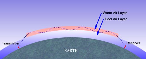
But one must also consider the Fresnel effect. If a hard object, such
as a mountain ridge or building, is too close to the signal path, it can
damage the radio signal or reduce its strength. This happens even though the
obstacle does not obscure the direct, visual line of sight. The Fresnel zone
for a radio beam is an elliptical area immediately surrounding the visual
path. It varies in thickness depending on the length of the signal path and
the frequency of the signal.
As
shown in the picture above, when a hard object protrudes into the signal
path within the Fresnel zone, knife-edge diffraction can deflect part of the
signal and cause it to reach the receiving antenna slightly later than the
direct signal. Since these deflected signals are out of phase with the
direct signal, they can reduce its power or cancel it out altogether. If
trees or other 'soft' objects protrude into the Fresnel zone, they can
attenuate (reduced the strength of) a passing signal. In short, the fact
that you can see a location does not mean that you can establish a quality
radio link to that location.
There are several
options to establish or improve the line of sight:
·Raise the
antenna mounting point on the existing structure
·Build a
new structure, i.e. radio tower.
·Increase
the height of an existing tower
·Locate a
different mounting point, i.e. building or tower, for the antenna
·Cut down
problem trees
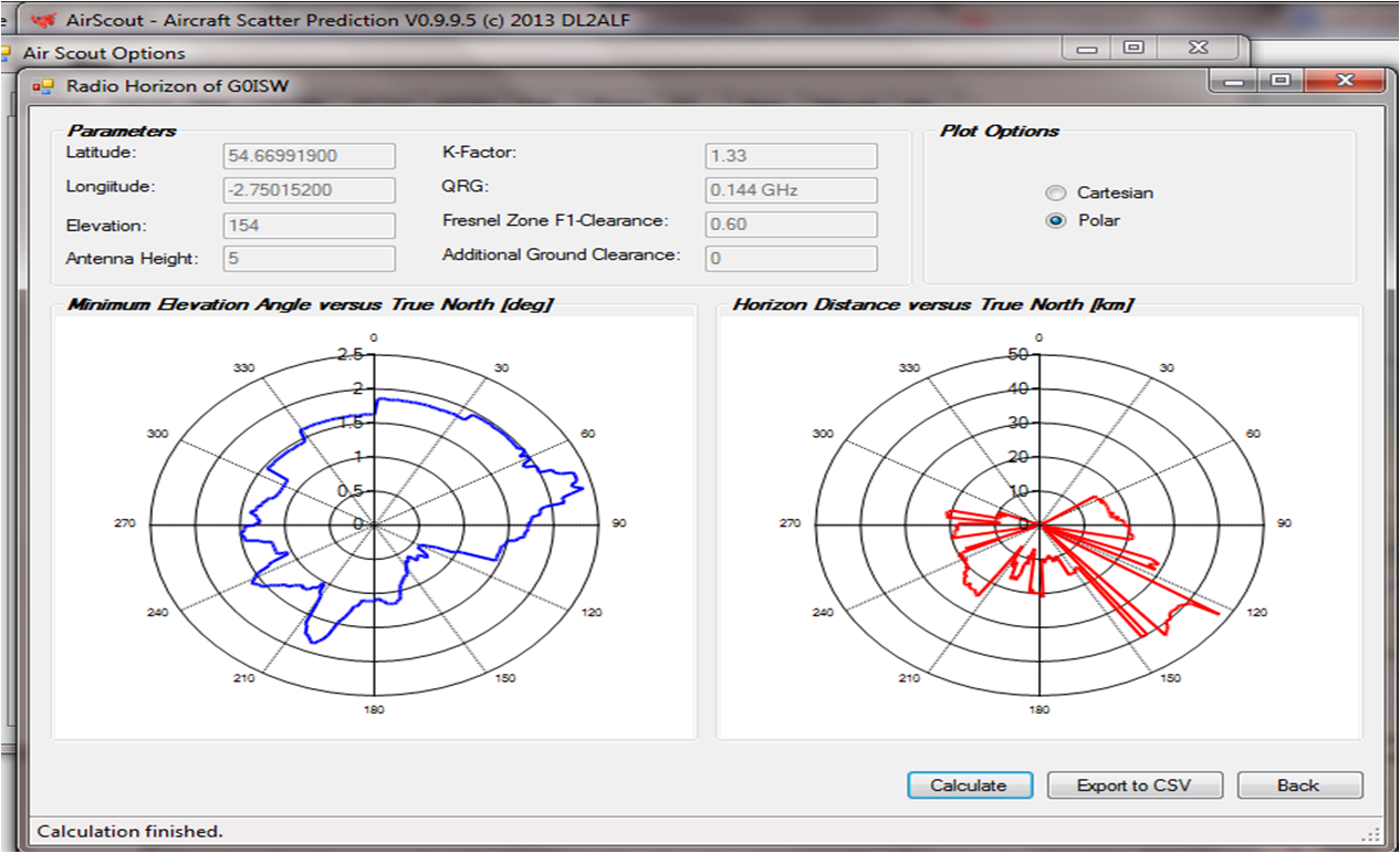
My own radio horizon is
obstructed by nearby hills and mountains as you can see in the charts below,
with the blue line being the profile of the
mountains as viewed and the red line being
horizon distances. Near 120 degrees I have an almost totally unobstructed
path in the region of a maximum 45 Km, whereas immediately behind my house
to the North I have a hill that blocks my signals in that direction.
Obviously if the transmitter is not located on the ground, but instead is in
an aircraft or balloon the line of sight distances can be vastly increased.
Example 4: Light aircraft at 3,000 m altitude, carrying Amateur radio
transmitter
Horizon Km = 3.569 x √ 3,000 metres =
195 Km
Example 5: Commercial
aircraft at 12,192 m altitude, carrying Amateur radio transmitter
Your LOS signal, which can be blocked by
high terrain can sometimes be diffracted or bent over the top of the
obstruction, particularly in mountainous areas if the top of the obstruction
is 'sharp', hence the term 'Knife-edge diffraction'.
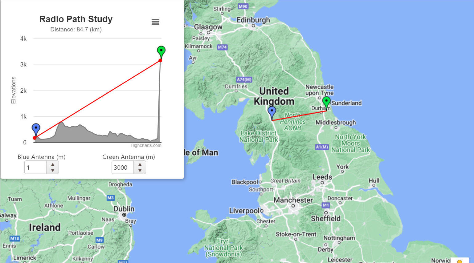
I live in a mountainous area and have
experienced a few instances where contacts have been made with stations that
should have been totally obstructed by high mountains in between. Single knife
edge or rarer double knife edge diffraction observations have been made by
me over the Pennine Mountains between Penrith and Hexham. The image below
shows the cross section and the distinct knife edges.
This propagation mode is available all the time and is the main one for longer
contacts, particularly at 144 MHz on SSB within
the UK or to mainland Europe. Slow fading of signals often apparent and
reasonable signal strengths.
Where your 'line of sight' distance has been exceeded due to the curvature
of the Earth or obstructions, this mode is the one most likely to be found
by radio amateurs, but does require typically horizontal steerable antennas
and SSB, rather than FM.
Particularly useful on the 144 MHz band where
from the UK it is possible to work nearby stations in France and Belgium all
the time. With high gain antennas and sensitive receivers Germany and
Denmark also become within range.
However this propagation type doesn't favour 50 MHz
so well and can be disappointing.
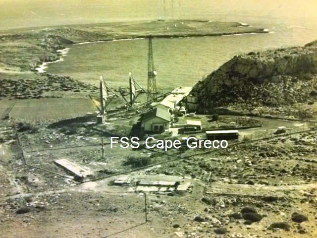
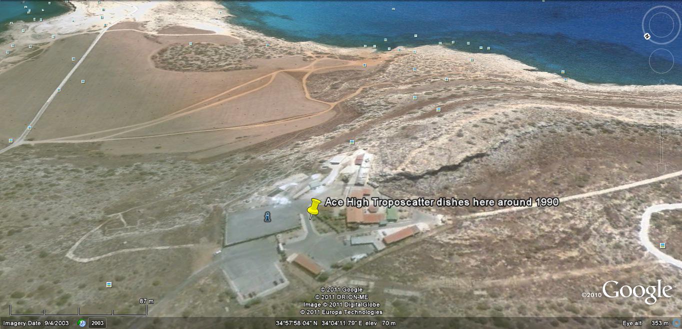
This
propagation mode was used by NATO, from around 1956 to the late 1980's, as
part of the
ACE HIGH
Troposcatter system on frequencies between 832 MHz
and 959 MHz, in a chain of
49 stations running
from Norway to Turkey. Transmitting power was around 10 KW and huge dish
antennas were used!
I
remember seeing the huge dishes at
Cape Greco (JCGZ) in
SE Cyprus in the late 1980's, but am struggling to find any photos of them
apart from this one.
Looking at Google Earth imagery below, from 2003, it appears the dishes have now
been removed.
Aircraft scatter propagation (ACS) has been regularly used successfully on
frequencies of 50 MHz and above. It can be subject to rapid fading of signals
at 144 MHz and higher frequencies and may not
be particularly easy to catch or use.
The higher the frequency used the better the results are likely to be.
Imagine bouncing your radio signals off the metal aircraft body,
which will be travelling at between 500-600 mph, in the same way you would bounce
light off a mirror. Due to the speed of aircraft transit, maximum 30 second
transmit periods are recommended and data modes such as
JT6M (30s periods) or
ISCAT-B (30 or 15 second periods) will probably yield the best
results.
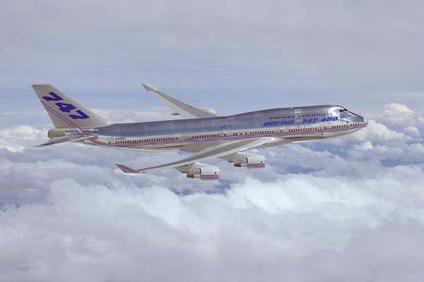
I
have often found using 50 MHz and
JT6M data
mode that identified Boeing 747 airliners are sufficiently large, with their
64m wingspan, to produce
good aircraft scatter. The scatter period on 50 MHz
can last up to around 1 minute if crossing the direct path between stations
and significantly longer if flying along the direct path.
Due
to the curvature of the Earth and VHF signals being line of sight there is a
maximum distance limit as to how far Aircraft Scatter (ACS) propagation can
be used. This maximum distance is approximately 758 km
for Civilian commercial aircraft reflections.
Also
this maximum theoretical distance using commercial airliners does not take
into account any path attenuation.
Using the calculations seen before for VHF line of sight signals we find that
for a signal from a commercial aircraft altitude to sea level, the
theoretical maximum radio horizon is
379 km as shown in the calculation below.
Example: Commercial
aircraft at normal maximum 11,276 m (37,000 feet) altitude, carrying Amateur radio transmitter
Horizon Km = 3.569 x √ 11,276 metres =
379 km (235 miles)
However, from my own recorded results the very best distance line of sight
to a Civilian commercial aircraft I have obtained has been
338 km (210 miles) due to nearby ground
obstructions i.e. mountains.
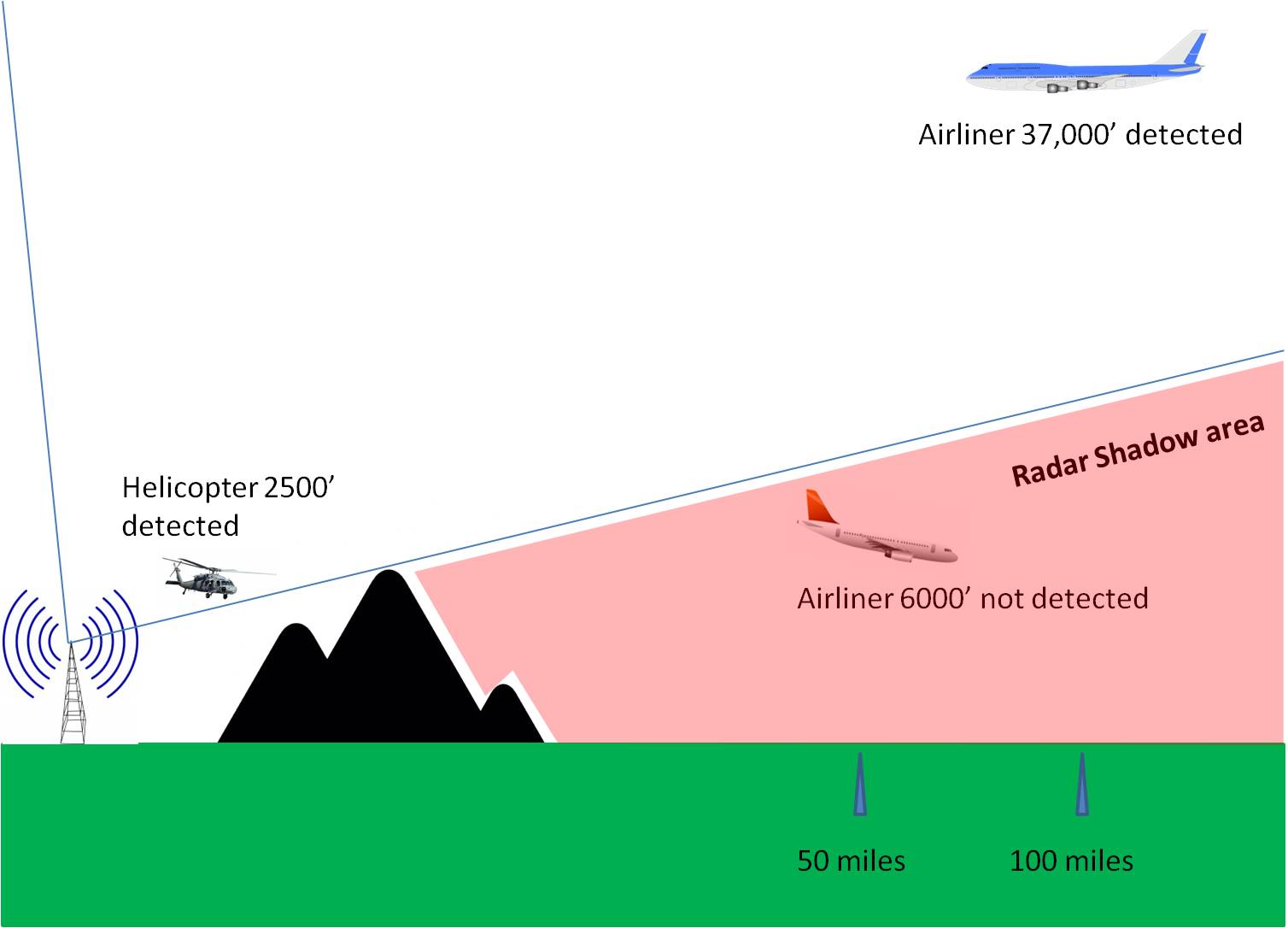
This zone of no line of sight could be referred to as a Radar Shadow Area (RSA),
see image below for a better understanding how closer aircraft can be hidden
yet further away higher aircraft ADSB transmissions can be observed.
Some modest increase in theoretical distance will be exhibited by amateur
radio stations being at an elevation above sea level. However even the top
of mountains will only add about 110 km more so
the distance could be extended to nearly 500 km
So
for the two legs from ground stations at mountain tops to aircraft and scattered back to
ground the maximum distance is 2 x(379+110) km = 978
km.
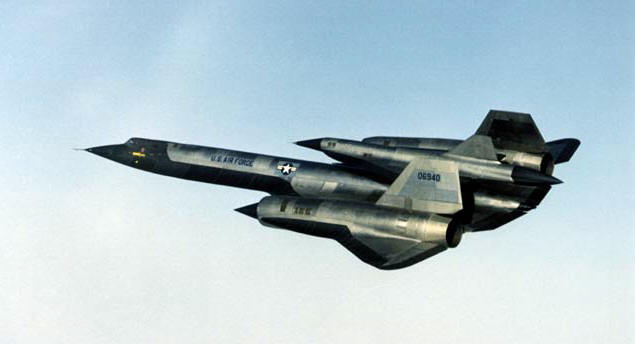
Do
any aircraft ever fly higher than 11,276 m (37,000
feet)?
Yes, historically the supersonic Concorde used to fly at a cruise altitude
of 18,900 m (62,000 feet) and the US Air Force SR71 Blackbird reconnaissance
aircraft set an altitude record in 1976 of 25,950m (85,135 feet) although it
is likely it could fly higher, but that maximum remains classified.
Some smaller modern military jet fighters apparently have a service ceiling
of 65,000 feet, but stealth radar absorbing materials used to avoid enemy detection
by radar will also prevent amateur radio aircraft scatter.
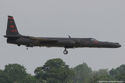
The only aircraft I have observed at significantly higher altitudes have
been rare U2 flights passing over the United Kingdom with a transmitted
height of 60,000 feet, although they could have been at a different higher
altitude apparently as anything over 60,000 feet is deliberately not shown.
There may be other classified experimental military aircraft operational
today, but due to the limitations of having air-breathing engines they too
are limited in maximum altitude.
If we use 25,950m (85,135 feet) as the maximum possible,
but most unlikely, theoretical and practical altitude then the radio horizon
would be:
Horizon Km = 3.569 x √ 25,950 metres =
575 km and for ground to aircraft scatter
and back to ground that distance would be doubled to
1150 km in theory!
Also
the aircraft size is key to whether or not is offers enough surface area for
the transmit frequency in use, at 50 MHz
(6m) it appears an aircraft the size of a
Boeing 747 with a 64m wingspan is required for good results.
Smaller identified aircraft such as Boeing 737, with 34m wingspan, have not
been observed by me to have as much success on 50 MHz,
surprisingly.
Realistically for all amateur radio purposes a theoretical maximum for
aircraft scatter (ACS) propagation remains around
700-1000 km for frequencies in the GHz microwave bands
Any
DX spots showing aircraft scatter (ACS) over this 1000 km
distance can only be operator error and should be discounted, with another propagation mechanism such
as MS or Es being the actual medium used.
RADAR (Radio Detection And Ranging) has used radio signals since before WW2
to determine the flight path of aircraft. Early German WW2 radar used
frequencies near to the amateur 144 MHz band.
Modern stealth aircraft such as the US Air Force F-117 were designed so that
their shape would not easily reflect Radar signals back to the receiving
station, by avoiding having any vertical angles.
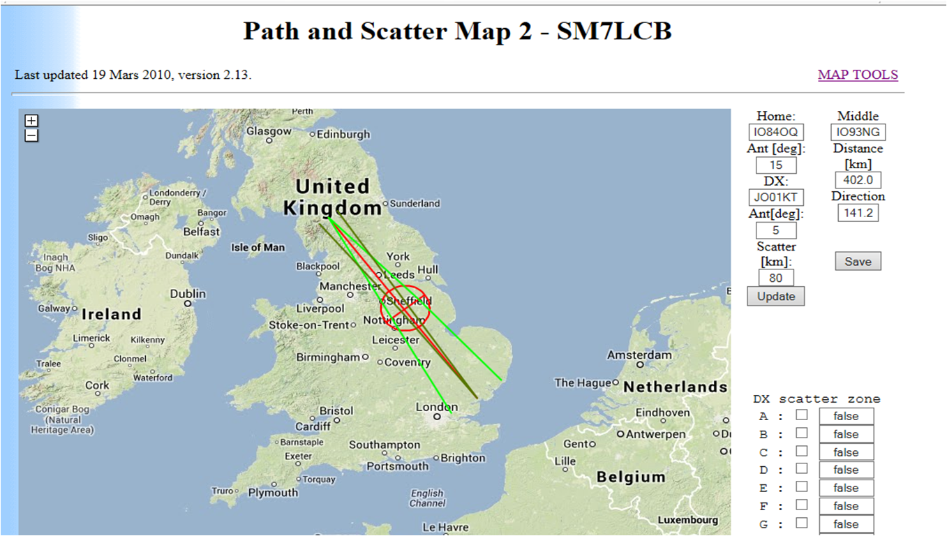
Some early experimentation has been done by
SM6FHZ and his
website detailing how to work regularly via this mode, using flight
timetables
is here.
Frequencies of 144 MHz,
432 MHz and 1296 MHz have all been used
successfully by him. Some imagery and an explanation of how you can experiment to
listen yourself can be found on the website of
G3CWI here.
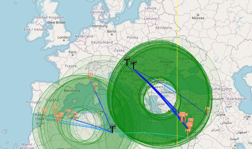
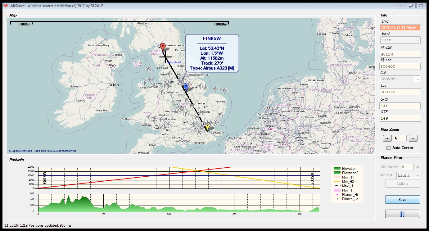
Since 2013 a
fabulous new piece of software called
AirScout has been
written by Frank DL2ALF especially for Aircraft Scatter propagation.
You get
moving aircraft over a map in real-time as well as a plot showing where your
signal and the station you are trying to work have a mutual reflective
scatter zone into which the aircraft can fly and their times predicted.
Additionally a path profile is generated which shows obstructions such as
mountains. This software is a superb tool to assist others
for ACS research and real-time working and of course fun!
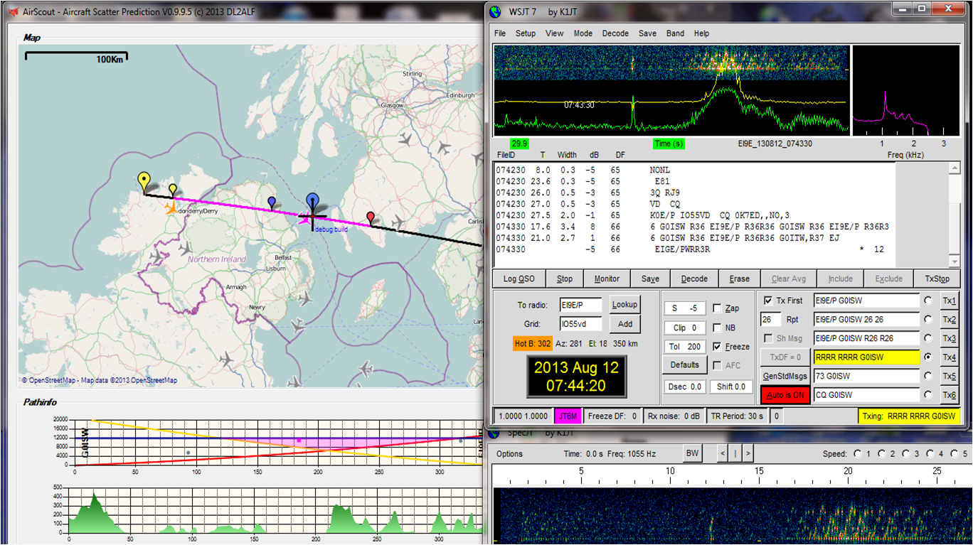
In the
Summer of 2013 I first experimented with this software and using WSJT
JT6M data mode
on 50 MHz SSB was able to take advantage of regular
aircraft scatter (ACS) between the UK and Ireland at a distance of
350 Km. The 30 second transmission periods for
JT6M fitted perfectly the 1 minute
long observed reflections, with fairly stable strong signal strengths seen. Happy days!
Since then I have had many successful contacts on 50
MHz using aircraft scatter and have even been able to predict the
reflections timed to the minute using
AirScout software by DL2ALF.
Signal strengths have been often observed at 6-12 dB.
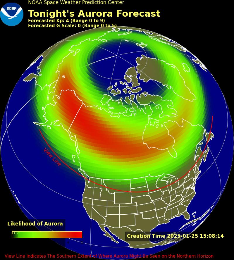
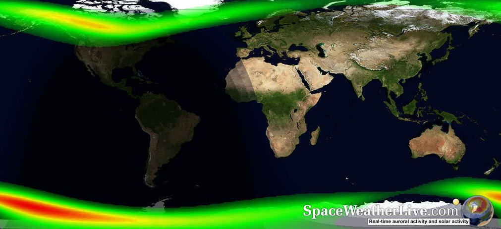
Aurora favours Northern
Europe. March is often a good month. You need to point your antenna between
North and East and reflect your signal off the moving Auroral curtain.
Speak much slower than normal and
compensate for the Doppler shift, which makes everyone sound like Daleks!
50 MHz is particularly good for this mode,
144 MHz is useable and
432 MHz is extremely difficult due to the high Doppler shift.
Field
Alignment Irregularities (FAI), can occur in the late afternoon from
May to August, and favour Southern Europe. The signal is usually
very weak and the scatter area is located at a height of approximately
110km.
This
Propagation mode seems to occur
when both stations are located at equal distances North and South of the
Magnetic Equator and experiencing a high level of electron density in Autumn and
Spring, usually during periods of solar cycle maximum activity and the equinoxes.
The
stations located over 45° of latitude north (or south) are usually too far
off the geomagnetic equator to make use of F-layer FAI. Sometimes however,
these latitudes could be worked via an additional sporadic-E hop/s, even if
signals are usually weak and typically exhibit the fluttery and hollow like
sound of pure FAI.
It was
observed prior to 2018 that there were two distinctly different types of TEP that could
occur:
The
first type occurred during the late afternoon and early evening hours and
was generally limited to distances under 6000 km.
Signals propagated by this mode were limited to the low VHF band (<60
MHz), were of high signal strength and suffered moderate distortion
(due to multipath). Single sideband voice communications were possible with
this mode.
The
second type of TEP occurred from around 1900 to 2300 hours local time.
Contacts were made at 144 MHz, and even very
rarely on 432 MHz.
The
signal strength was moderately high, but subject to intense rapid fading,
making morse code (narrow band CW) the only possible communication mode. One
amateur described the signal quality in the following words: "we tried SSB
but there was so much distortion that not a single word could be identified.
[this mode] has a lot of flutter and fading and ... even the morse comes
through like a breathing noise, not a clear tone" (from the Dawn of Amateur
Radio in the UK and Greece by Norman F Joly).
Events in 2018 for the Australian station of
VK8AW working stations in Europe on 50 MHz
at solar cycle minimum via TEP combined with
Sporadic-E have now thrown previously accepted observations and
theory out of the window. This appears due to the new weak signal data
mode FT8 which is allowing two way communications via TEP to be successful
even at solar cycle minimum, with the Middle East and China both being heard
most days at his station near Darwin in Northern Australia.
It also appears that
VK8AW being ideally situated just within the
TEP zone at -40 degrees latitude and having a very high gain
50 MHz station, using weak signal data modes,
has been able to regularly observe four (4) separate TEP waves each day and
not just two as previously thought.
This has been observed
again in June 2019 with EA8 stations working Japan on 50 MHz apparently
using a combination of TEP + ES
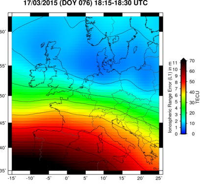
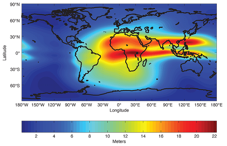
The
following vertical total electron content map from NASA may help to indicate
whether or not propagation via TEP is more or less likely.
Right Click on image
below and select 'open link in new tab' for live data.
Here
below is an old image from 2012 clearly showing the very high Total Electron
Content shown in red colour as two distinct areas equidistant North and
South of the Magnetic Equator, which in all probability was very likely to
have been a TEP path for VHF radio signals at that time.
Here is a
further example from the European Space Agency
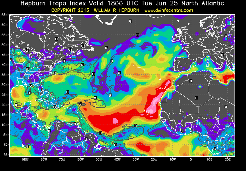
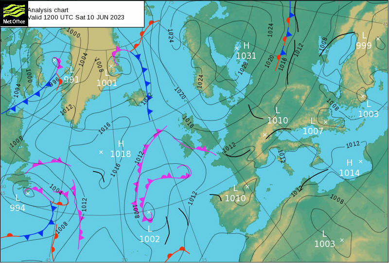
Signals can be quite strong. Look for periods of high air
pressure over the UK and Europe. Often extensive fog can indicate the right
conditions for this propagation mode. Once established paths can be open for
many hours or days. Often you may hear far away 144
MHz/432 MHz repeaters that normally cannot be heard.
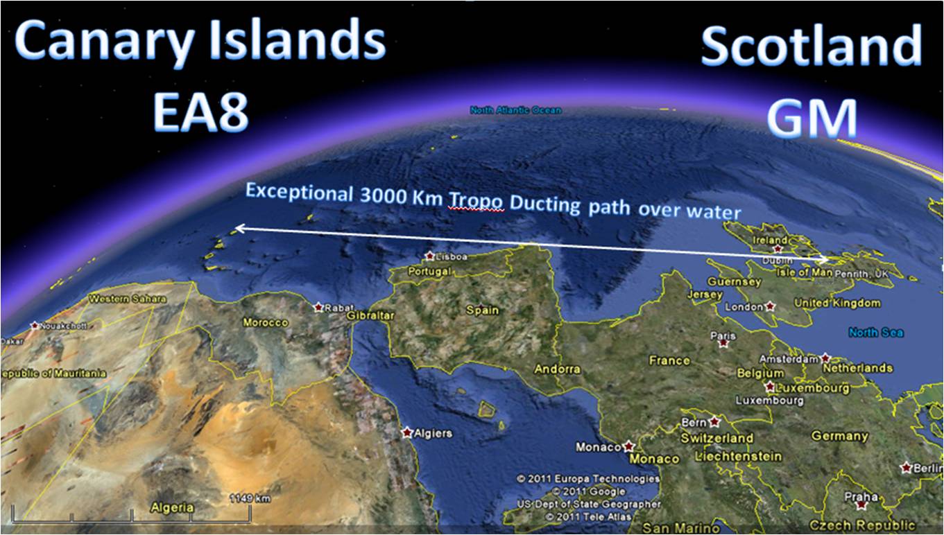
Sea paths possible
exceptionally up to 4700 km on
144MHz SSB, paths between Scotland and the Canary
Islands have been worked several times. The IARU Region 1 record for two-way
communication on 144 MHz was set at
4163 km in 2018
between EI3KD and D4Z using CW on the Cape Verde islands, the maximum
distance heard earlier in the day was as far North as GM around
4700 km which is astounding.
October often
the best month.
These Ducts form at heights between 450m to 3000m, but are blocked by higher mountains along the
path. They require stable High pressure areas, fog can be a good indicator.
Select Europe map and then click on
site to view
readings. Gif image to 700mB best. Look for
temperature inversions, where the inversion thickness layer is
wide enough to support ducting at 144 &
432MHz, using the table below.
Not commonly useable by
radio amateurs. Ionoscatter is the scattering
of radio waves in the ionosphere due to irregularities in the electron
distribution, which causes changes in the refractive index. Scattering is most
pronounced in the D-region between 70 and 90 km and is best from
30-60 MHz.
Ionoscatter is a
propagation mechanism available 24H a day like meteor scatter, but it is
different from meteor scatter. Ionoscatter deliverer's a continuous weak
signal and does not have the characteristic bursts in signal strength of
meteor scatter.
Ionoscatter starts about
900 km and extends to almost
2,000 km. Troposcatter works on all frequencies
50 MHz to 10 GHz,
whereas Ionoscatter is only useable on 30-60 MHz.
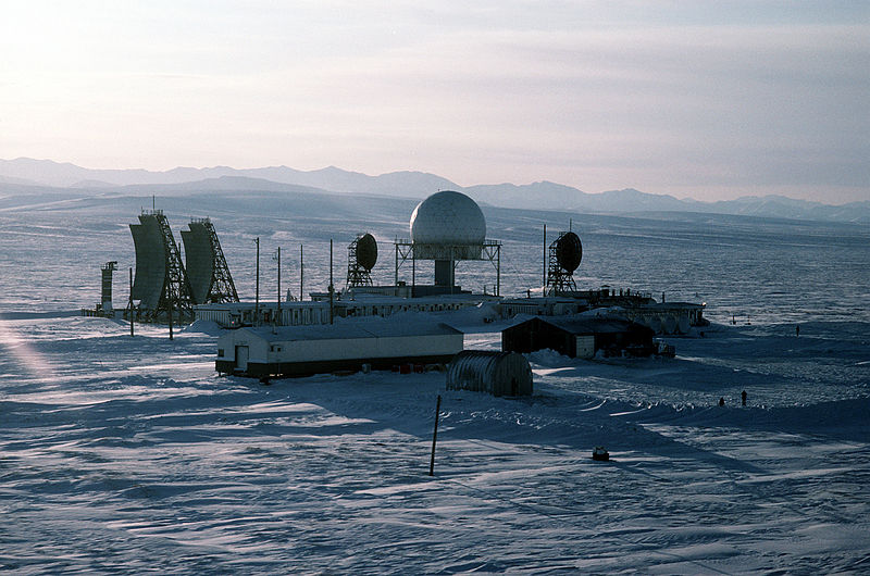
NATOMilitary radio systems from around the years 1950-1960 used
huge aerials and around 40kW of power to
maintain reliable signals via this mode! The Distant Early Warning Line
DEWLine
being a good example. Therefore it is rare for Amateur
Radio transmissions to be powerful enough to utilise this mode. The Military Ionoscatter system was replaced by Troposcatter systems
in the 1960's.
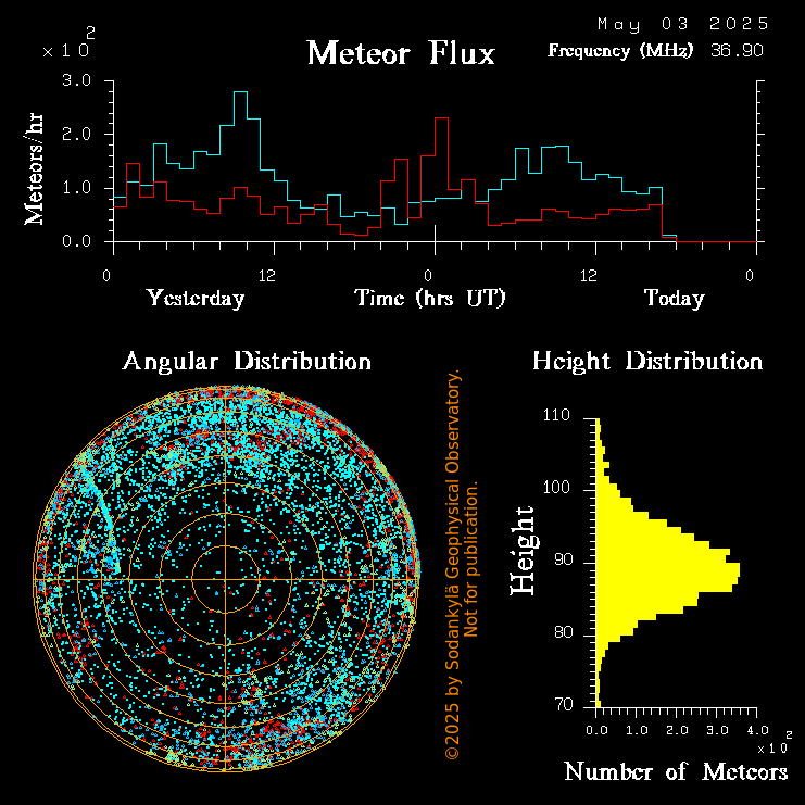
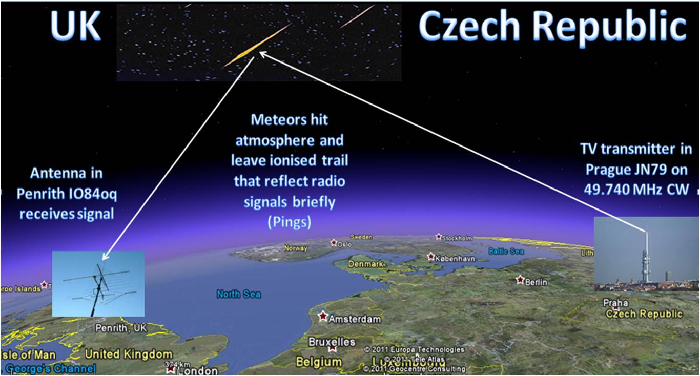
Most meteorites have a significant iron
metal content and when they burn up in the atmosphere at heights between 85-90 km
they leave behind metallic ionised trails which reflect VHF signals back to Earth,
that would otherwise be lost in space. Signals are typically of very short
duration, but can be strong typically from -2 to +13db. During the rarest
and most
intense meteor showers the duration of signal reflections can be several
minutes.
Extremely rare, once or twice in a
lifetime, events can have so many meteors hours burning up that the E layer
permits reflections lasting for several hours, just like Sporadic-E propagation.
I have only ever witnessed this once with the Leonids shower in November
2002, with 700+ meteors per hour being recorded.
Summer months are best for the major
showers, but winter months are active too. Random meteors occur all the time, day or night, and there are far
more meteors than can be seen visually. Can be a mode that
can revolutionise 50/70/144 MHz SSB contacts using
software such as WSJT or
MSHV by LZ2HV
(latest MSK144 mode with 15 second intervals, is very popular in 2017) for long distance contacts. My favourite
propagation type!
The lowest distance 500 km MS contacts can be very difficult to complete due
to the high angles required, fewer meteors trails being in just the right
place and nearby radio signal obstructions such as mountains, mid distance
MS contacts around 700-1200 km being far easier.
Whilst most stations use directional horizontal beams and 100W or more,
success can be achieved with omni-directional antennas such as horizontal
loops and surprisingly even with vertical colinears.
The DX record for MS is somewhat over 2350 km,
however this may be by the use of at least two different propagation
mechanisms, for example MS + Sporadic-E or Tropo Ducting, as the curvature
of the Earth and meteor heights set physical limits for pure MS QSOs.
Reflections of radio signals can last from around 250 milliseconds (1/4 of
a second) to 30 seconds plus, but the vast majority are extremely brief. It
can take a long time to complete a QSO in the region of 30 minutes or an
hour, unless there is a major Meteor shower.
In November 2002 the Leonids storm was the best ever with over 2300+ meteors
each hour. So many meteors were striking the atmosphere that an almost continuous
reflective layer was formed with amazing easily completed verbal QSO's with Sporadic-E signals that lasted for many hours continuously
on even 144 MHz.
For Meteor Scatter the 50 MHz band is by far
the best, 144 MHz is usable too, but more
difficult and 432 MHz and higher almost unheard
of.
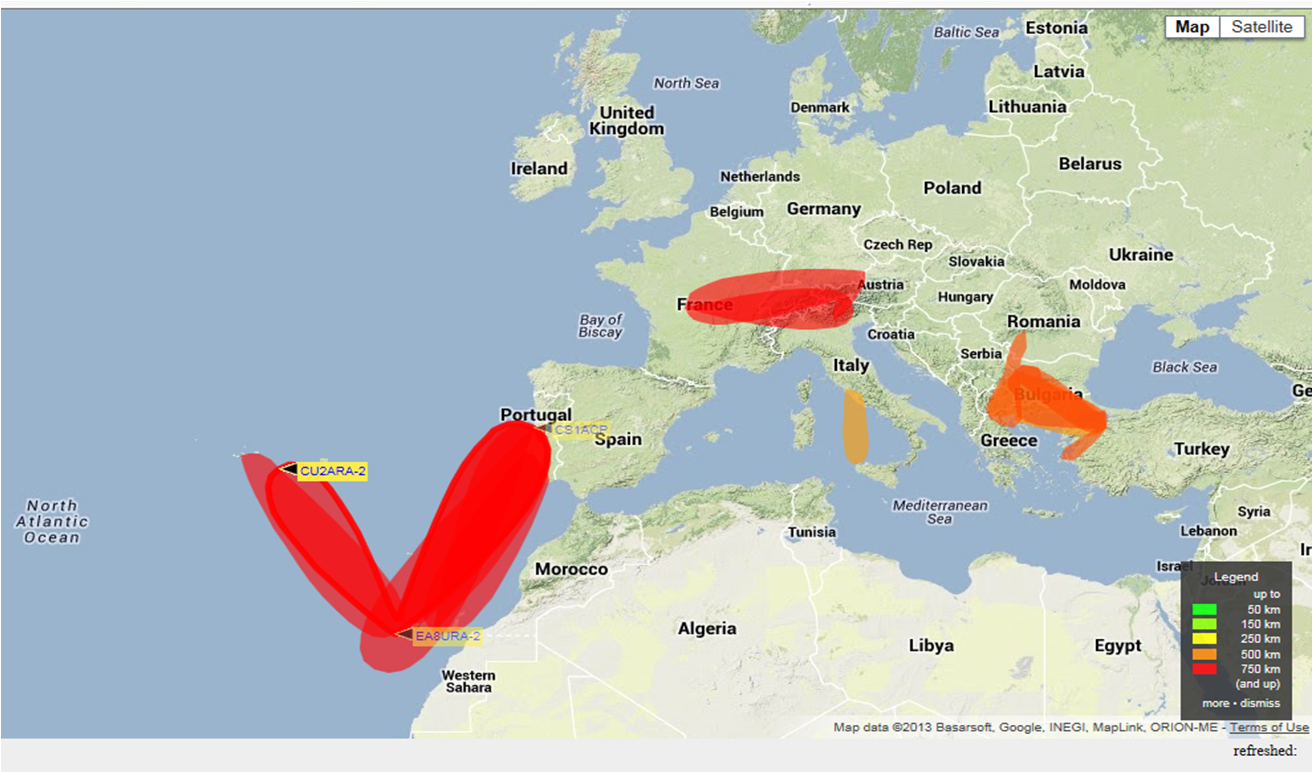
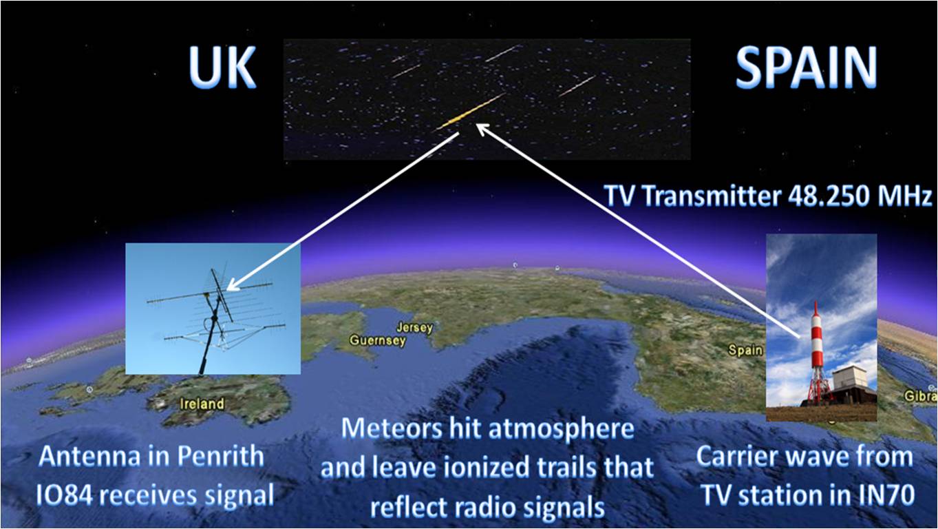
To easily hear Meteor
pings tune your transceiver to a distant strong VHF Band 1 TV station video carrier
or VHF FM Radio station and you will hear nothing until the signal is
reflected briefly by a passing meteor! Please note that during the Summer
months
Sporadic E (Es)
may allow you to hear the TV or radio carrier continuously.
The Spanish TV Transmitter shown above, closed down in 2010, but in 2011 the
TV Transmitter in Prague shown below was active. Sadly almost all Band 1 TV
stations are closing down, replaced by UHF digital instead.
Unfortunately Band
1 analogue TV has been phased out in Western Europe and so the availability of these
TV carriers is being much reduced for monitoring Meteor Scatter. There are
some alternatives, such as the
French GRAVES
space surveillance radar system on 143.050 MHz CW.
Sporadic E (Es)
is an abnormal propagation mode
at mid-latitudes which occurs mainly during the Summer season, from
May to August in the
Northern hemisphere and from November to
February in the Southern hemisphere. Very strong signal strengths are
common, particularly in the peak month of June in
Europe.
There may be a few further Sporadic-E events at other times of year,
especially during larger Meteor Showers
Intense solar radiation and high metallic meteor deposition rates are
required. The
reflection takes place in a thin layer up to a maximum thickness of
4 km varying in altitude between
90 - 130 km
above Earth, (often around 110 km) the higher
the height of the Es cloud the greater the distances that can be
worked as the angles of reflection are shallower for those stations furthest
apart.
The
Es Maximum Useable Frequency (MUF) varies from 20 MHz
to at least 220 MHz with the primary limits for
minimum and maximum distances for Es signals being the geometry of the
Earth, electron density of Es clouds and their height. Maximum path distance
will occur just below the MUF cutoff.
The ionisation clouds can sometimes be observed to drift westwards at speeds of few hundred km per
hour. There is a weak periodicity noted during the season and typically Es
is observed on 1 to 3 successive days and remains absent for a few days to
reoccur again, a bit like charging up a battery and then depleting it.
The
Sporadic-E cloud sizes vary those capable of reflecting radio signals at
50 MHz tend to be in the region of around 500
km x 500 km, whereas for 144 MHz they are often
only 50-100 km in size. It is often found that nearby amateur radio stations,
some recorded as only 5km away from you, can work stations you cannot hear and vice versa, it all depends on
where that Es cloud is.
Es do not typically occur during the darkness hours,
the events usually begin at dawn, there is a peak around 12:00 UTC and a
second peak in the evening around 16:00 UTC. Es propagation is usually gone by
local midnight.
For the UK 50 MHz Es propagation favours
stations located furthest South, however openings for Northern based
stations do occur, but
interestingly often an hour or more later than for stations in the London
area. This
can result in big pileups with stations around London being worked by the DX
station, only for an hour later stations in the North getting a look in!
This can be most frustrating as the DX station may well go QRT by then or
the pileup is so huge that the more Southerly stations with stronger signal
strengths are the only ones heard.
Sporadic E (Es)
clouds on 144 MHz have been observed to initially occur 'sometimes' within approximately
150
km (90 mi) to the East of a severe thunderstorm cell complex in the
Northern hemisphere, with the opposite being observed in the Southern
hemisphere. To complicate matters is the fact that
Sporadic E (Es)
clouds that initially form to the East of a severe thunderstorm
complex in the Northern hemisphere, then move West of the severe thunderstorm complex in the Northern
hemisphere.
So one may look for
Sporadic E (Es)
clouds on either side of a severe thunderstorm cell complex. Things
get even more complicated when two severe thunderstorm cell complexes
exist approximately 1000–2000 km apart.
Not all
thunderstorm cell complexes reach severe levels and not all severe
thunderstorm cell complexes produce
Sporadic E (Es).
This is where knowledge in Tropospheric physics and weather
analyses/forecasting is necessary.
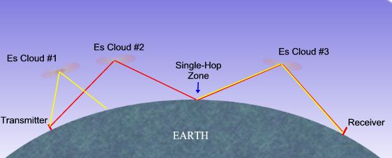
50MHz 2,400km is max
'single' hop distance.
50MHz
Sporadic E (Es)
season is
usually from
May to August in the Northern Hemisphere,
peaking
in June. 'Double' or 'triple' hop often seen
vastly increasing the distances worked.
Some distances worked
when at solar minimum in 2007 or solar maximum in 2013 have been in the order of
6000km, via triple hop Sporadic-E. On 20th June 2013 there was a
50 MHz Es opening from Europe to the Caribbean that vastly exceeds double
hop distances. On 12/13th June 2018 triple hop Es to Brazil in South America was
observed by me on 50 MHz here in IO84 square.
Some theories suggest these double hop Es occur from the Es layer clouds not
being flat, but having an irregular or bumpy surface which can reflect the
radio signals to other clouds before returning to Earth. Or some theories
favour reflections from bodies of water on the ground back
to the Es cloud layer.
On
50 MHz rare x4 Es hops have been observed
between Europe and Japan, these have been seen in July 2023 over an entirely
daylight path in the early morning UK time, before sunset in Japan.
Sporadic E remains a mystery, since first
observed in the 1930's.
144MHz 2,350km is max single hop distance.
144MHz
Sporadic E (Es)
season
is from June to July in the Northern Hemisphere,
with the peak in June.
Signals often very strong but areas within the reflection zone are very
pronounced, often spots are seen in one part of the UK with other parts not
having the same luck.
Only open on 50MHz
at the peaks of the 11 year solar cycle. For the Northern hemisphere in the Winter months
open from October to January and possible from
Europe to work all Continents, including Australia.
Last peaks I observed F2 propagation at 50 MHz was in
2024
and
2013
If you like my website, please consider making a small donation using the
'buy me a coffee' link below, thank you