From: Abe Riazi ([email protected])
Date: Sun Jan 16 2000 - 18:46:04 PST
Doug Smith Wrote:
>I am interested in ways that people use to verify simulation results,
>that is to check that the results reflect reality.
Dear Doug, Others:
Useful insight can be gained regarding the procedures for
verification of simulation results by considering four common types of
SI simulations (namely impedance, crosstalk, flight time and waveforms )
and how evaluated.
IMPEDANCE
Impedance of microstrip, striplines, Low Voltage Differential
Signals (LVDS) and Single Ended (SE) configurations can be investigated
via simulation. Following methods are often used towards verification
of the output:
i. Mathematical computation utilizing well established impedance
formulas.
ii. TDR Measurements (if feasible).
iii. Utilizing rules of thumb. Two useful ones include:
For a 50 Ohm microstrip trace w/h = 2.0 (where w = trace width h
= dielectric thickness).
For a 50 Ohm stripline trace w/b = 1.0 (where w = trace width, b
= total dielectric constant. Reference: Eric Bogatin, "Rules of Thumb I
Have Known and Loved").
CROSSTALK.
There are several excellent programs available for crosstalk
simulation. The concepts of forward and backward crosstalk can prove
helpful when evaluating validity of the simulation outcome.
Furthermore, the following two expressions are frequently utilized when
analyzing crosstalk results:
1/[1 + (D/H) **2]
Ls = Vp * Tr/2
The first expression indicates how the maximum value of crosstalk
varies as a function of center to center trace separation D, and trace
distance from plane H. The second equation relates saturation length
Ls, propagation velocity Vp and signal rise time Tr.
FLIGHT TIMES
When inspecting flight time data, it is important to take into
consideration the allowable limits (imposed by the setup and hold timing
budgets). As an example, for simulation of 33 MHz PCI bus, the maximum
flight time values allowed by the specs are about 10 to 11 ns. When a
flight time value violates such limits, it is recommended to carefully
inspect the associated waveform and ascertain the causes. In one
simulation of a 32 bit bus all of the data lines indicated flight times
less than 10 ns with the exception of one net which showed a flight time
value of 25 ns for a particular driver/receiver combination. Additional
analysis revealed that the long flight time was due to a "bad route".
WAVEFORMS.
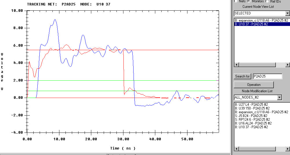
An example of a simulation waveform is presented below:
In the above example, although the net included multiple devices,
only the waveforms associated with one driver and one receiver are shown
to maintain simplicity. Incidentally, the receiver waveform (in blue
color) contains effects due to diode kick back which was recently
described by Scott McMorrow. As mentioned earlier, waveforms associated
with the nets showing flight time violations demand a more detailed
analysis, in order to determine what types of SI violations (i.e.
overshoot, ringback, ringing, etc.) are occurring. I have observed
numerous instances of long flight time violations caused by ringback.
Waveform interpretation often requires paying close attention to
details such as peaks and dips aimed at determining the associated
causes (i.e. impedance discontinuities, fast driving edges, diode
flyback effect, etc.). Furthermore, whenever possible TDR and
oscilloscope measurements are recommended to allow correlation of
simulated output and the measured data. Once the nature and the causes
of SI violations have been identified, then possible means of reducing
or eliminating them ( for instance, changing technology, alliterating
topology or incorporating termination) have to be analyzed.
frrequently, during a simulation certain assumptions and
approximations are made (for example, the surface roughness or
transmission line losses may be ignored) to simplify the simulation
task. The level of inaccuracies introduced by these approximations
should be quantified or proven to be negligible.
Employment of high quality calibrated models are often a necessity
towards production of reliable simulation results. Generating accurate
simulation results may also require a deep understanding of the
capabilities and limitations (i.e. frequency limits, convergence
problems, bugs and patches) of the simulator algorithm, and recognizing
the meaning and significance of the warning or error messages that the
simulator program may flag during the course of simulation.
In closing, mathematical computations, detailed data analysis,
physical measurements, and utilization of rules of thumb combined with
judicious reasoning are among the means employed in determining the
validity of a simulation result.
I hope you find this information useful.
Best Regards,
Abe Riazi
SI Engineer
Anigma, Inc.
>

**** To unsubscribe from si-list: send e-mail to [email protected]. In the BODY of message put: UNSUBSCRIBE si-list, for more help, put HELP.
si-list archives are accessible at http://www.qsl.net/wb6tpu
****
This archive was generated by hypermail 2b29 : Thu Apr 20 2000 - 11:34:42 PDT