![]()
![]()
![]()
![]()

|
|
|
|
By Jan Buiting, PE1CSI, Philips Mobile Radio Collection, Sibbe, The Netherlands. Email [email protected] Article originally published in Radio Today September 2000, updates included in this web version. Warning: the Simple Conversion described here has been tested on the following radios: FM1100 RA911, FM1200 STM22, FM1200 STM23, FM1100 SU0, all with the numeric keypad head. Warning: The Simple Conversion is not suitable for FM1200 radios with a Type-1 control board. This includes the ex Electricity Systems VHF FM1200 SB014 which is around in vast quantities in the UK. This radio can only be converted by means of the Extensive Conversion. IntroductionProvided you can get hold of the right versions, the Philips FM1100, FM1200 and FM1300 PMRs (Personal Mobile Radios) are probably the easiest converted ex-PMRs for amateur use. About the FM1200 UHFIn all likelihood, any Philips PMR Type FM1200 STM22 found on rallies, car boot sales etc. was at some time part of a large trunking radio network operating in the UHF band. The FM1200 was originally designed around 1990. This once very advanced, very expensive microprocessor controlled FFSK transceiver consists in essence of three modules:
The three modules that make up the radio communicate via an internal bus en simple pinheaders and sockets. The original EPROMs contain about 32 or 64 Kbytes of machine code for the 80C31s. Years ago, at the Simoco headquarters in Cambridge, the FM1200 was jokingly called ‘a computer acting as a radio’. The FM1200 version STM22 supplies 25 watts of RF power, is suitable for the 12.5 kHz raster, and covers 400-440MHz. In other words, it should be ideal for radio amateur use. The radios in the FM1000 series are easily assembled for local control (i.e., with the console mounted on to the radio) or for remote control (console mounted on the dashboard and radio somewhere else in the car). The conversion described here was first tried out by Gerrit Speelman PA1MT. Since then it has been carried out more times than I care to remember, with a good success rate. The conversion typically takes less than 15 minutes to complete. All the designing, debugging and head scratching has been done for you and comes in the form of this web document and three ICs: two EPROMs and one EEPROM. As far as transmit power levels are concerned, the FM1200 STM22 puts competing UHF radios like the SE Condor 46 and some other ex-carphones to shame. In practice, 25 watts of RF is a comfortable level to have available on 70cms, providing much more ‘push’ than a 6 or 10 watts rig, especially when going mobile. The conversion consists of three steps, or, if your like, 'phases'. To begin with, new software is fitted in the console (EPROM). Next up is the only bit of solder work you'll have to do: relocating a single PCB track. This effectively puts the internal trunking processor to sleep, enabling the FFSSK FM1200 to behave like a regular NBFM transceiver. Next, we fit a new ‘firmware’ EPROM in the radio itself. Finally, a suitably reprogrammed EEPROM is fitted. This is an 8-pin IC containing about 1,000 user settings. FM1200 conversion, step-by-stepGeneral tips
Converting the console
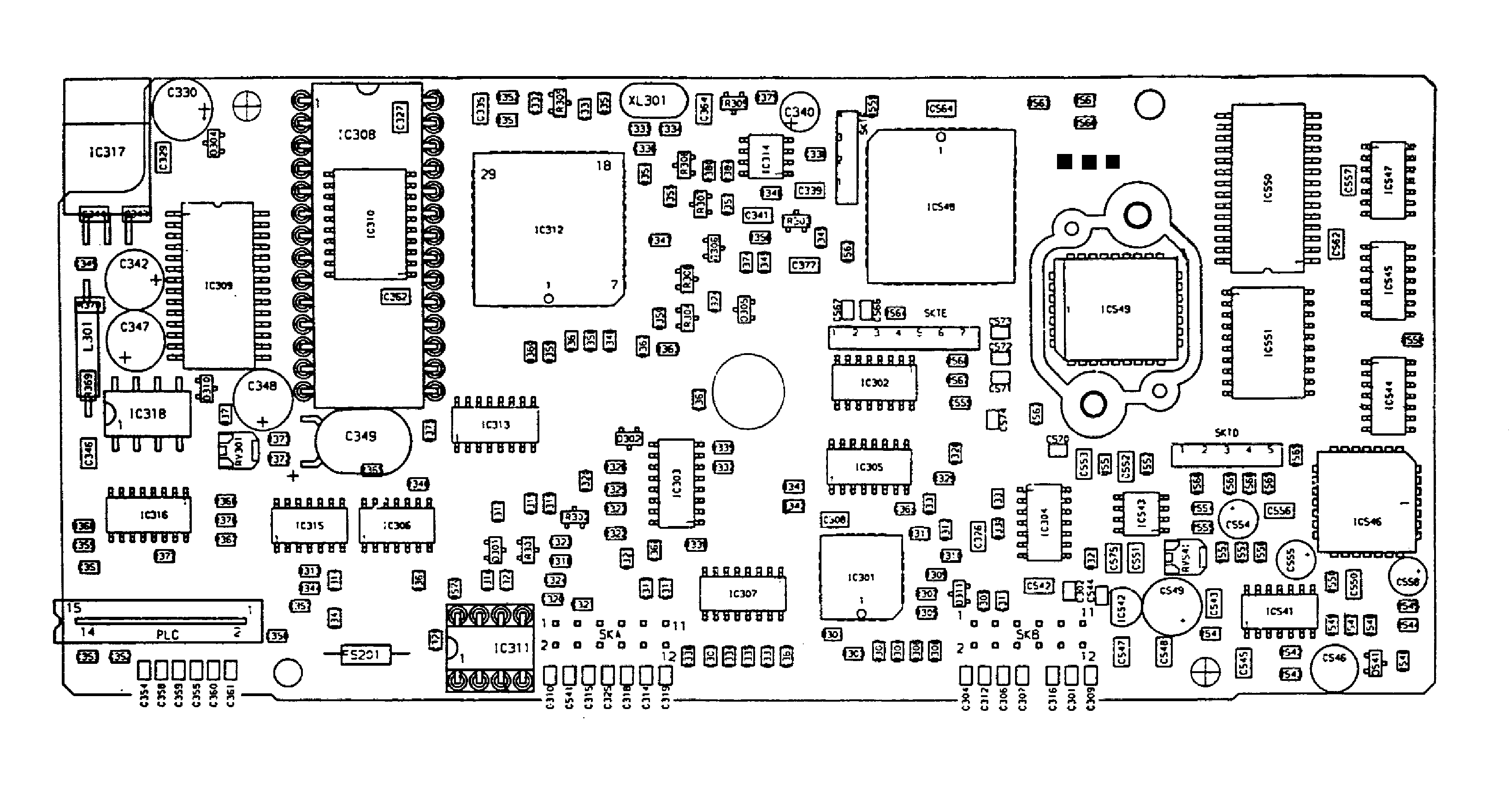
Converting the radio proper
FM1200 TestingUse heavy-duty (min. 2.5mm2 csa) wire for the supply cable, and insert an in-line slow-blow fuse rated at 10A. Connect the microphone, power supply and loudspeaker. If your set came without a connector/cable set, look at the drawing below to find out the pinout of the supply/LSP connector on the rear of the radio (rear view of connector). Pin 8 (Ignition) is usually permanently connected to the positive wire (+12 V).
Set the supply to about 13 volts and switch on the radio using the pushbutton on the front panel. Sometimes the radio produces a short 400Hz tone. The display will indicate the loudspeaker symbol in the top left-hand corner. To the right, you will see the start-up frequency and below it the associated channel number. Current consumption at this point should be less than 600mA with the LCD backlight turned on. If you get ‘Undefined Error Code 03’ then the radio will contain no or incorrect user data in the EEPROM. First connect a dummy-load and then key the transmitter. RF power should be in excess of 25 watts (I measured 28 watts on a Bird Thruline, and 26 watts on a Marconi TH1035). FM1200 additional informationThe program and data in the EPROM installed on the control board originate from the FM1100, the 'non-trunking' sibling of the FM1200. The program and data in the display head EPROM were developed out of an example taken from an FM1100. Mind you, the frequencies and texts that appear on the LCD are held in the console EPROM, not (unfortunately) in the EEPROM! The process of display text customization is explained here. All radios from the FM1000 series look identical and are, in principle, produced for any PMR band between 50MHz and 550MHz. So be sure to read and understand the type number! The STM22 is a hit for 70cm amateur use. When purchasing an unknown ‘FM1000’ radio, make sure you are aware of the number/letter combination indicating the frequency band, bandwidth and transmitter power. The FM1200 SK111 seems to be around in vast quantities (ex trunking systems in Band 3) but it requires major hardware surgery because of its unusual frequency range (K1 band = 175 to 208MHz). The transparent film you will have found on the LCD is, of course, intended for the original application of the radio. Using the original film, a graphics program, a laser printer and some transparent sheet it is easy to make a new film with the appropriate legends on it. An ordinary copy machine is also suitable, although professionals will of course have nothing less than real acetate film. In the table on the File Downloads page I've included film designs for the FM1100 and FM1200. Loading a different set of frequencies is only possible if you have rather special equipment available capable of directly writing into the EEPROM using a prescribed format. This equipment is called PDP (Portable Data Programmer) or CDP (Computer Data Programmer). As part of my collection of vintage Philips PMR stuff I happen to have a PDP Level 3 and a Factory Level CDP (FDP7). OperationBecause the modification was designed to be as simple as possible, the radio is pretty Spartan when it comes to the user interface. Do remember however that the FM1200, like many other ex PMR equipment, was never designed to act as an amateur radio transceiver. None the less, an FM1200 converted according to this recipe should be perfect as a simple mobile rig for a couple of fixed channels or a local 70cm repeater station. The quality of the modulation has been judged as 'excellent' throughout. The converted FM1200 is simple to operate. Press the CH(annel) key and enter the channel number. The associated frequency will appear instantly on the display. You can start transmitting straight away by pressing the red PTT button on the microphone. The knobs for 'squelch defeat' and 'low power' will be used less often. The channel/frequency allocation for UK, Dutch (NL), German (DL) and Finnish (SF) radio amateurs is given as a an Excel spreadsheet on the File Downloads page. The first two dozen or so channels are reserved for 70cm repeaters. Unfortunately the FM1200 does not have an internal 1750 Hz call tone generator, 5-tone calling or CTCSS, so that you have to add these options your self using suitable hardware. Fortunately, the microphone has enough space to allow a miniature 1750Hz tone call board to be fitted. The FM1100After this fairly extensive description of the FM1200 I can be brief about the FM1100. Make sure you get the subtype RA911 (20 kHz channel spacing), VA911(25kHz) or SA911 (12.5 kHz). The FM1100 only requires the two EPROMs and one EEPROM to be replaced to turn it into a 25-watt 2m band transceiver with 100 channels between 144.5000 and 145.9250 MHz. As opposed to the FM1200, the FM1110 does contain the required ICs for 1750 Hz tone calling, variable 5-tone calling to various standards and even variable CTCSS (TX-Only). The latter option is however only possible after a small hardware modification to the control board. The result of this conversion job (well, exchanging three ICs) is a robust transceiver. Operating the FM1100 is largely identical to the FM1200, but with 5-tone calling and CTCSS added. Press the * button and then enter the 5-digit code you want to transmit. The tone sequence is sent by pressing the red button. The same for the CTCSS: first press SETUP, then select the desired subtone (for example, code 02 = 71.9 Hz). Enable CTCSS by pressing the CTCSS button. The selected subtone will be transmitted along with your speech signal on the current channel. If CTCSS is switched on, the receiver will be blocked for all incoming signals not containing the selected subtone. A 1750 Hz tone is transmitted for about 1.5 seconds by pressing the grey key on the microphone.
|
|
Last modified: February 15, 2002 |