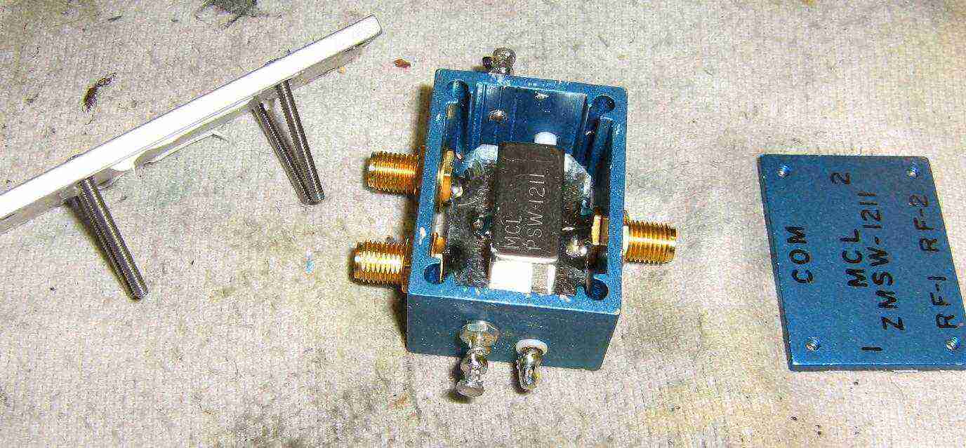
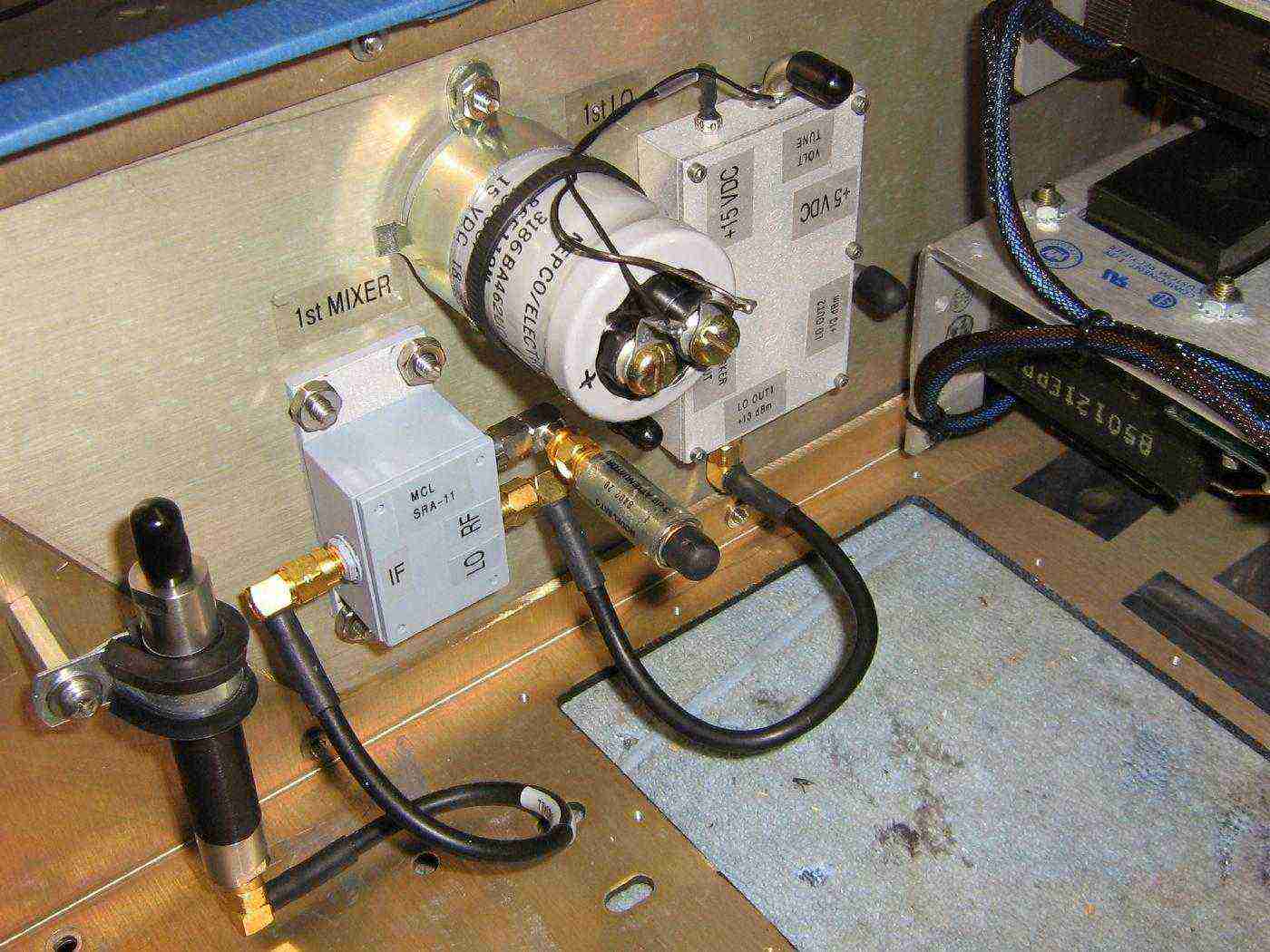
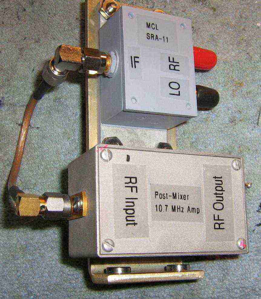
Using a surplus Mini-Circuits ZMSW-1211 PIN diode switch case for holding a Mini-Circuits SRA-11 mixer.
ZMSW-1211 PIN diode switches are often available at swapfests for very low cost and the aluminum case they use (and PC board pattern) are perfect for converting into RF mixers.
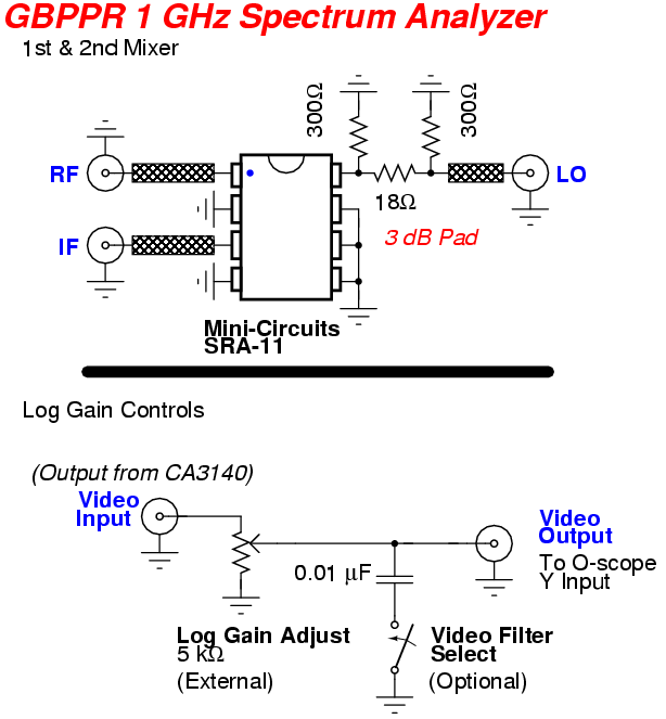
There are probably much better mixers for use in this spectrum analyzer project, but I got these SRA-11 mixers for free. The "ideal" mixer will have 40+ dB isolation between the LO and RF ports. Note that the first mixer will have the incoming RF signal (DC to 1000 MHz) on its IF port. This is done as the IF port has a better low frequency response than the other mixer ports.
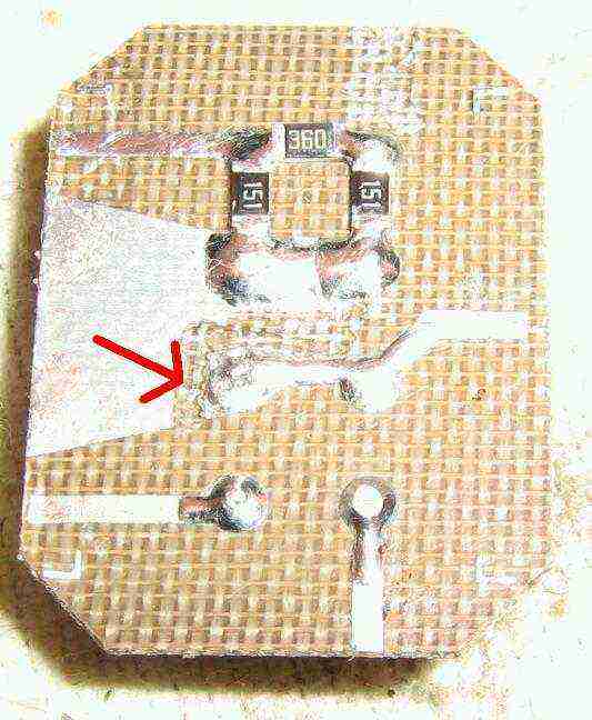
Modifying the PC board of the ZMSW-1211 PIN diode switch to fit a SRA-11 mixer.
Isolate the SRA-11's pin 3 on both sides of the PC board by grinding away the copper using a Dremel tool.
A resistive 3 dB attenuator pad will be added to the LO port. Note the picture shows components for a 6 dB pad.
Pinout for the Mini-Circuits SRA-11:
LO        Pin 8
RF        Pin 1 (Blue Ring)
IF        Pin 3
Ground    Pins 2, 5, 6, 7
Not Used  Pin 4
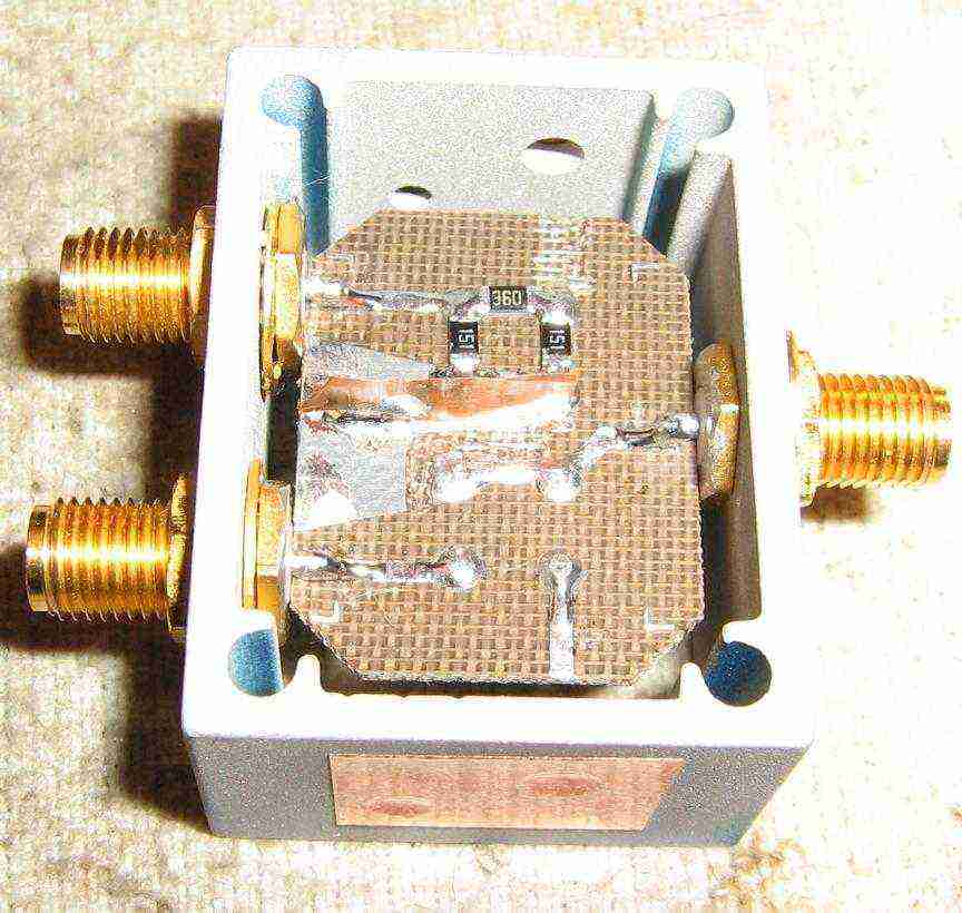
Putting the new SRA-11 mixer together.
A small little copper shield was added to further help isolate the LO and RF ports.
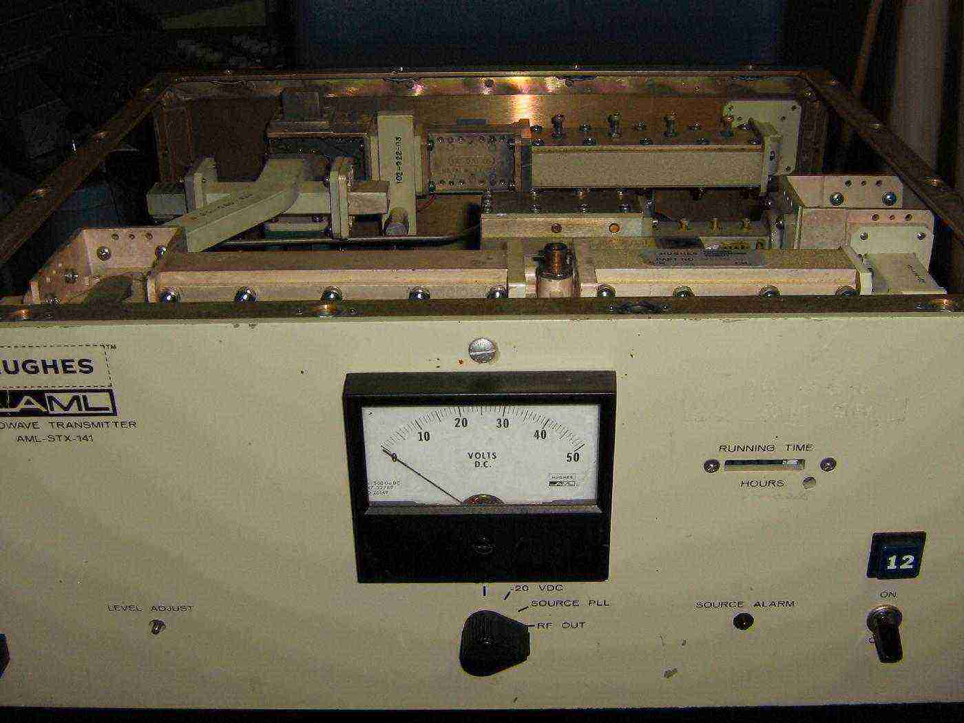
This spectrum analyzer project will be housed in in an old Hughes AML-STX-141 Ku-band CATV link transmitter case.
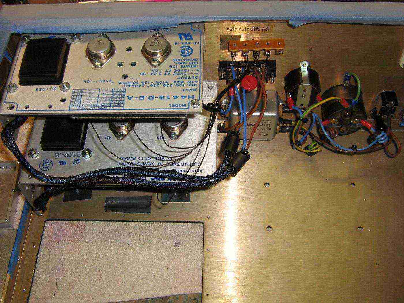
Power for the modules will be provided by two linear power supplies. Don't even think of using switching power supplies - as most are too noisy.
One power supply provides +/- 15 VDC and the other is for +12 VDC.
The +12 VDC power supply will be used for powering auxiliary items like relays, lights, etc. to help keep the main +/- 15 VDC power lines clean.

Incoming 120 VAC mains power.
The AC sockets were stock to the AML-STX-141 and an AC line filter, fuse, MOVs, and power switch were added to the rear-panel.
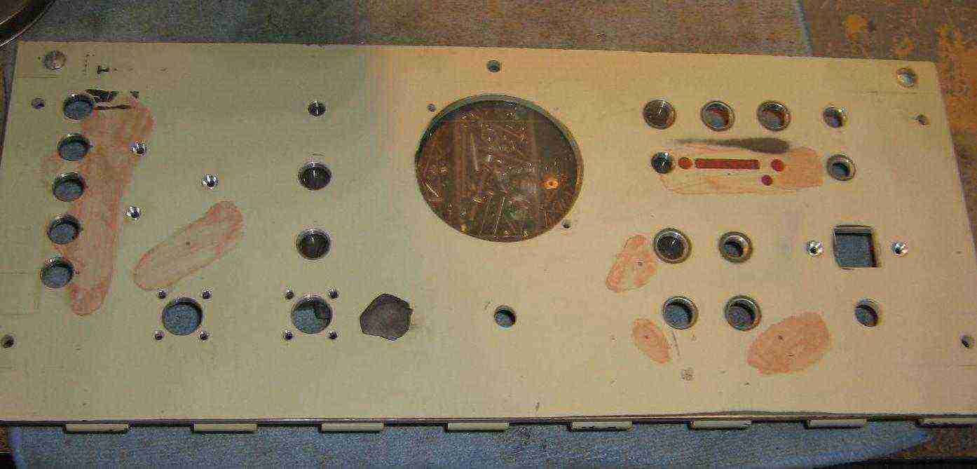
Modifying the front-panel of the AML-STX-141 to house all the controls for the spectrum analyzer.
Standard auto body repair techniques were used to fill in any unsed holes.
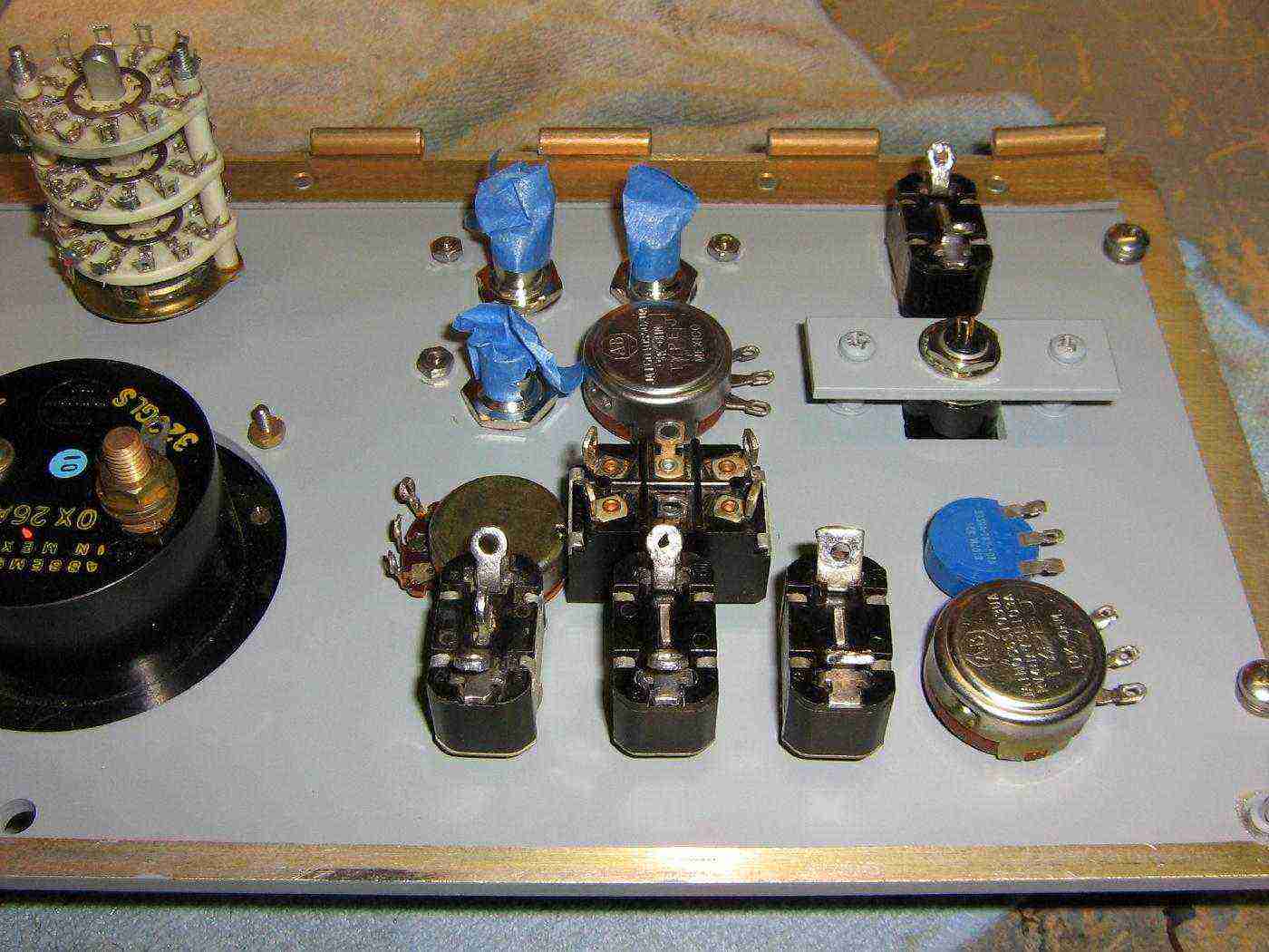
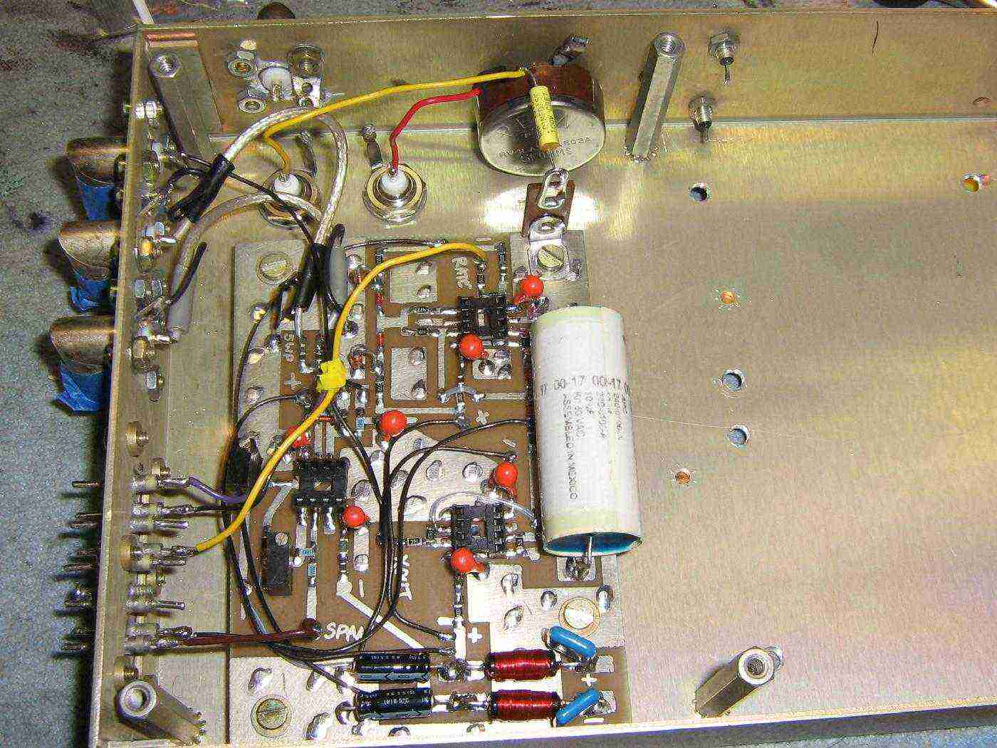
Behind the finished front-panel showing some of the switches and sweep generator controls.
The meter will not be used at this time.
Potentiometer on the lower-right is for Sweep Rate.
The blue potentiometer is for Fine Tune.
The multiturn potentiometer on the bracket is for Coarse Tune.
The switch above the multiturn pot is for Zero Span.
The potentiometer to the left of the multiturn pot is for Sweep Width.
The BNC jacks are for the oscilloscope X and Y outputs and a tap for the VCO sweeping signal.
The other switches for things like the marker generator, resolution and video filters, and controls for a future FM demodulator.
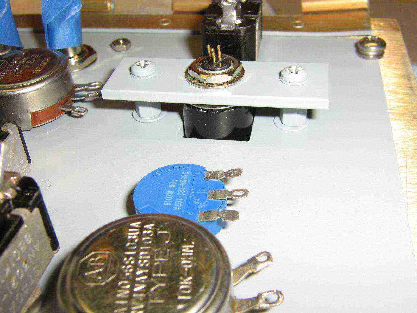
Coarse tuning control was a multiturn 10k ohm potentiometer with a turns counter from an old Tektronix 1502 TDR.
This pot required a little mounting bracket for proper operation.
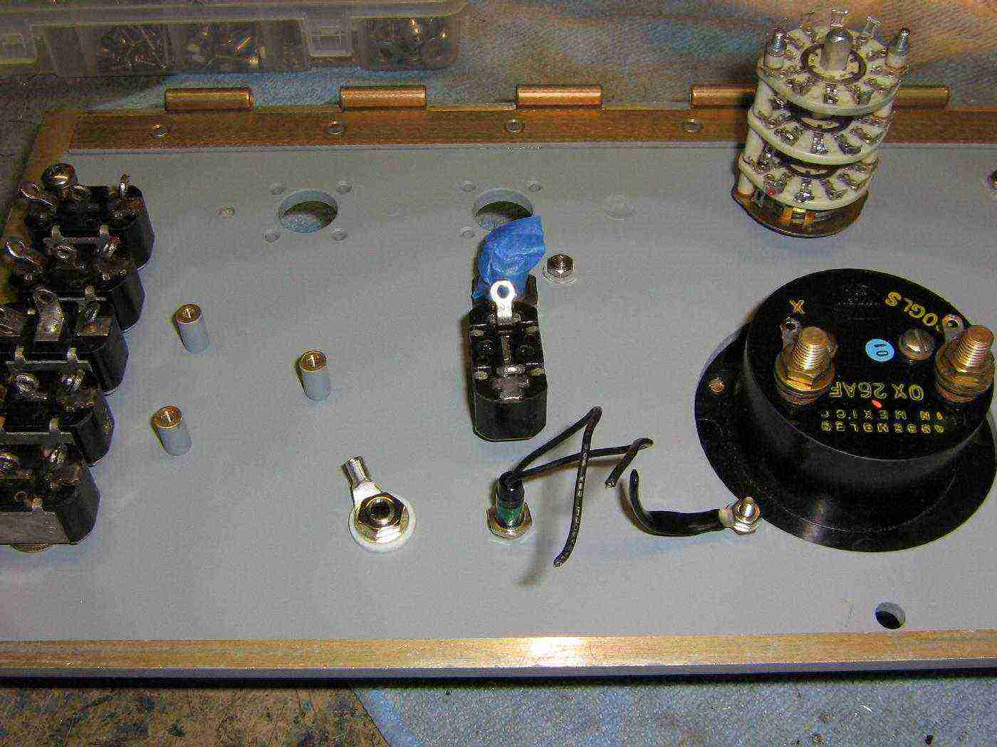
Behind the finished front-panel showing some of the switches for the RF input section.
The three little standoffs will hold an optional Hittite HMC307 31 dB attenuator evaluation board.
The switches on the left control the attenuator controls (1 to 16 dB).
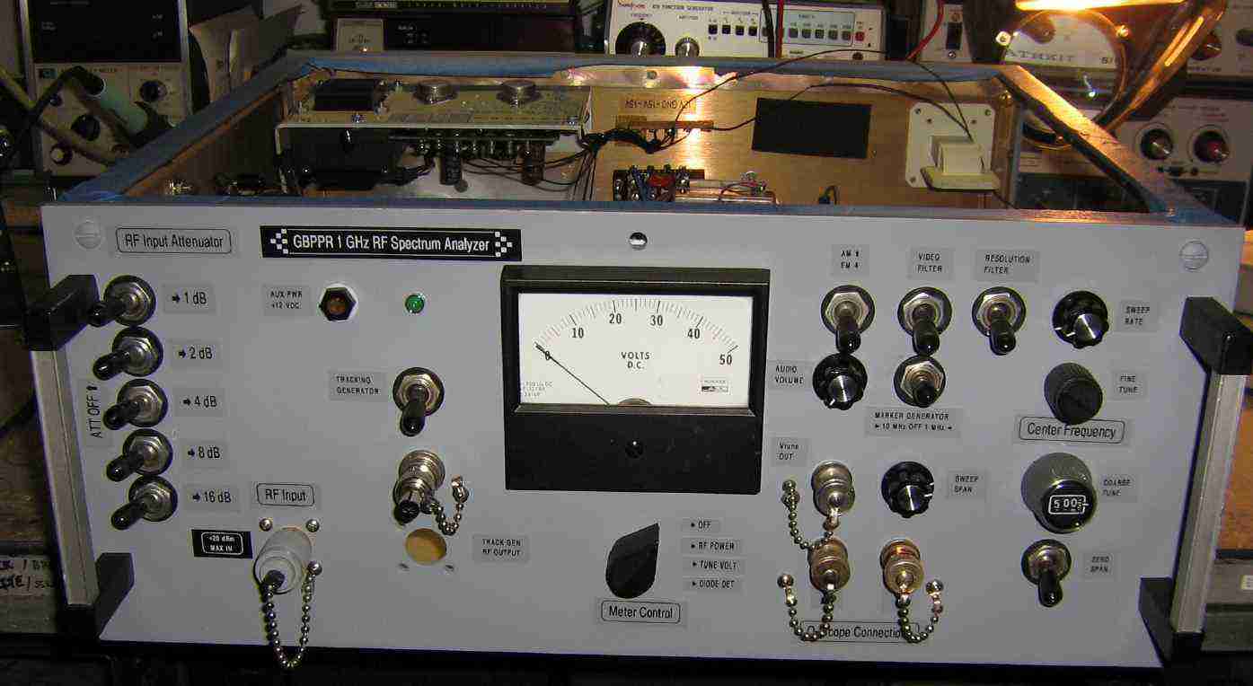
Completed front-panel overview.
Some of the switches (and meter) are not in use right now, and will be reserved for future upgrades.
Yes, I bought a Brother P-touch label maker...
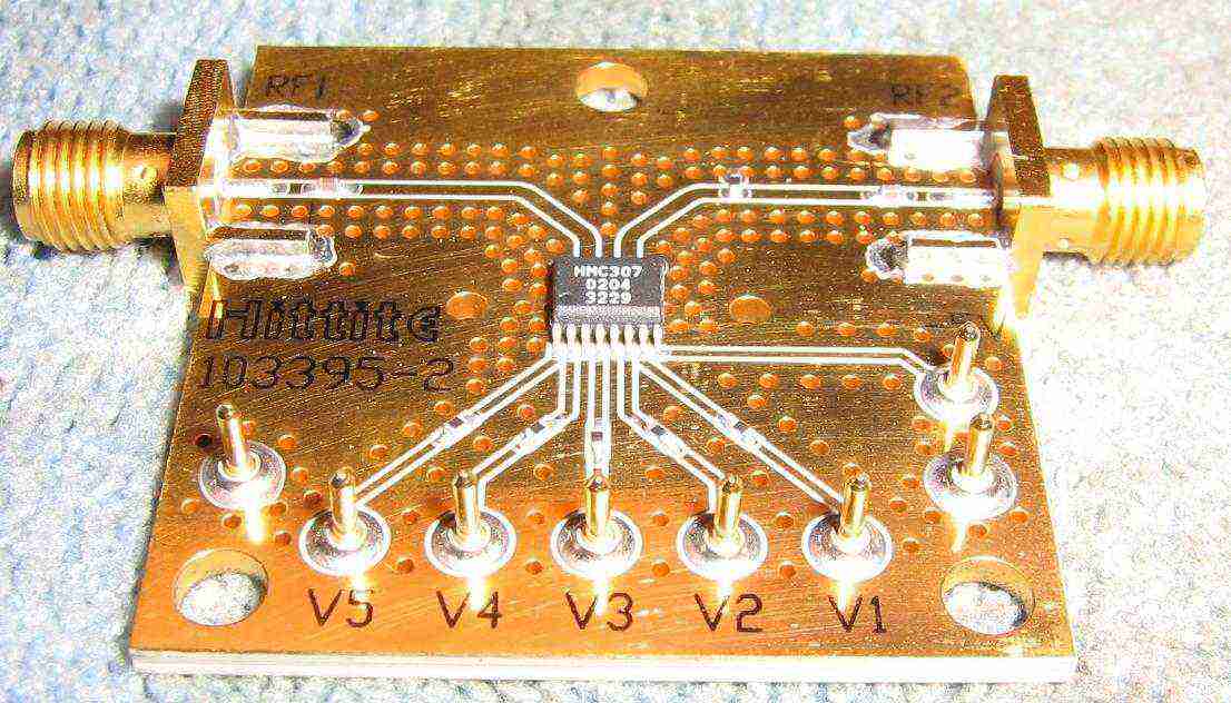
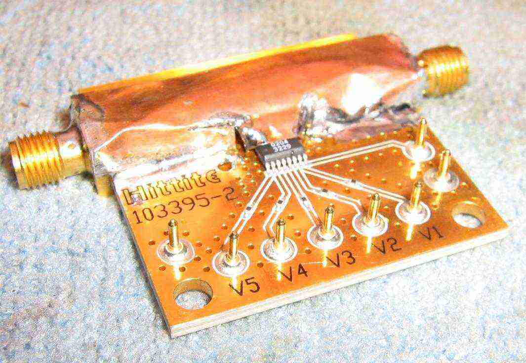
Hittite HMC307 31 dB step attenuator evaluation board.
This is optional, but an input RF step attenuator is very handy on your spectrum analyzer.
This particular step attenuator can be easily controlled using only toggle switches on the 1, 2, 4, 8, and 16 dB control lines.
The Hittite HMC307 runs at -5 VDC which is regulated down from the main -15 VDC supply line. The control lines also operate at -5 VDC.
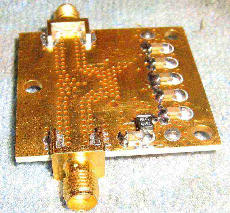
A few minor modifications were made to the Hittite HMC307 evaluation board.
Surface-mount 0.01 µF capacitors were added to the control lines and a 2.2 µF capacitor was added to the main power line.
A copper shield was added to help prevent external RF interference.
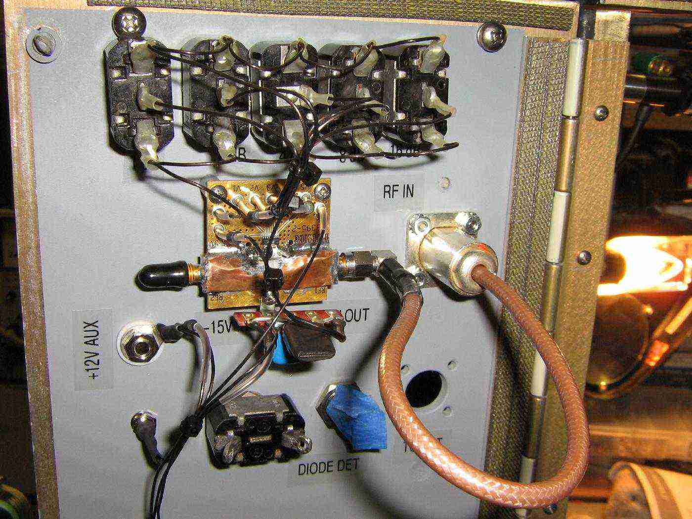
Mounting the Hittite HMC307 evaluation board and connecting the RF input line.
RF input to the spectrum analyzer is via a panel-mount N jack.
A 7905 voltage regulator is mounted on a solder terminal block to power the Hittite HMC307 evaluation board. The toggle switches control the -5 VDC going to the HMC307's attenuator control lines (V1 to V5).
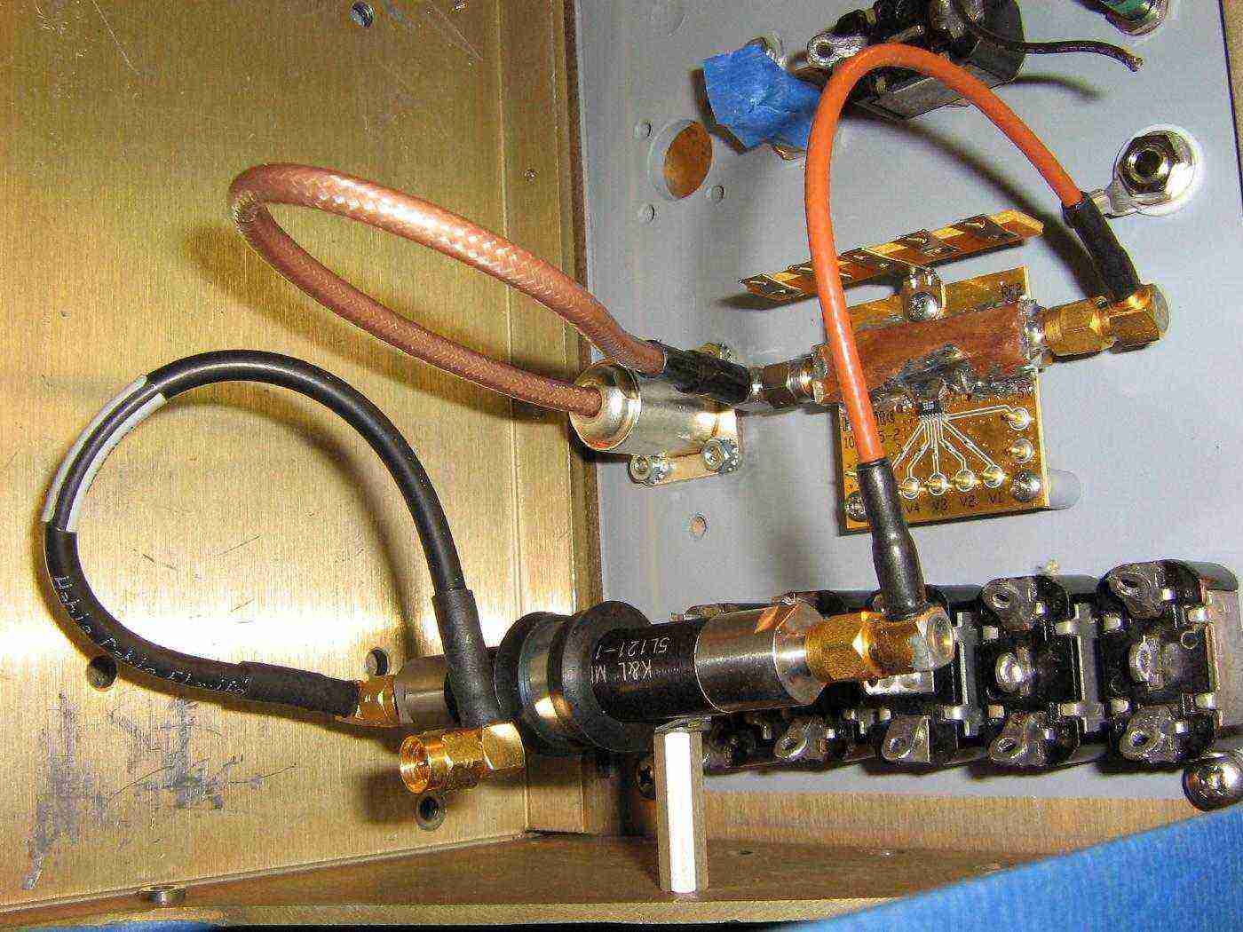
After the step attenuator is a 1000 MHz low-pass filter.
This is to prevent higher (out-of-band) frequency signals from becoming spurious images in the spectrum analyzer's display.
This particular low-pass filter is a K&L 5L121-1000/T5000-O/O. It's a five section low-pass filter with a 3 dB point at 1000 MHz and an insertion loss of around 0.65 dB. This filter was found at a swapfest. A Mini-Circuits equivalent would be the SLP-1000.
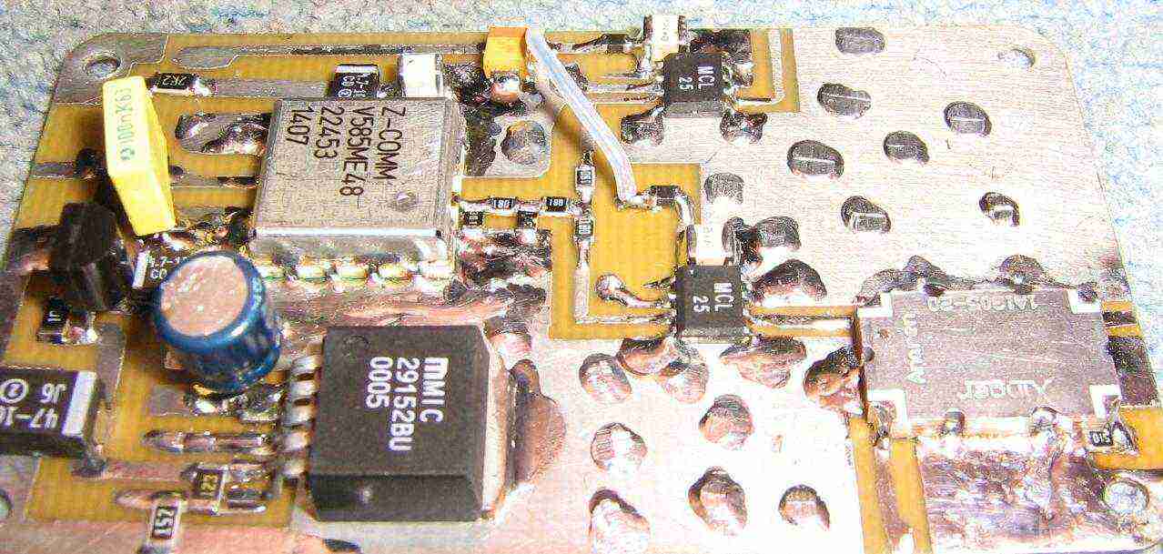
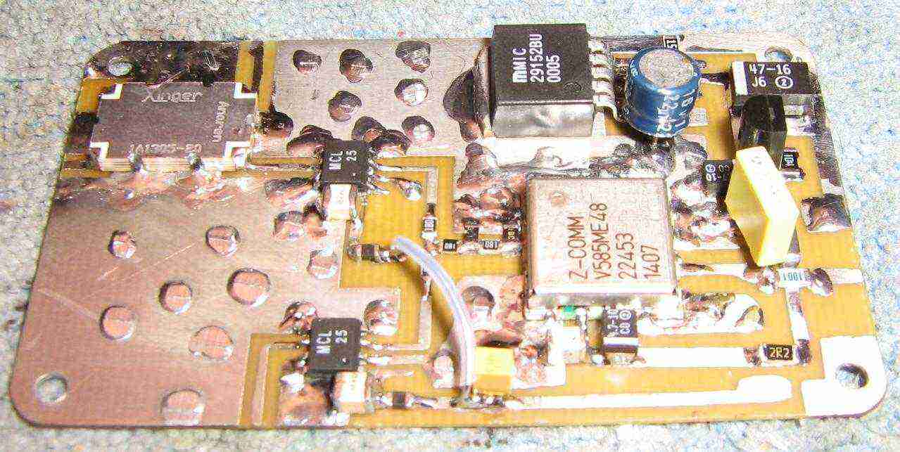
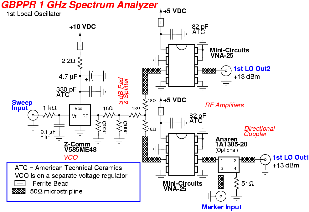
First local oscillator circuit.
Based around a Z-Communications V585ME48 VCO sweeping between 1013 - 2013 MHz and feeding two Mini-Circuits VNA25 RF amplifiers. One of these outputs is going to the local oscillator port on the first SRA-11 mixer, and the other output will be used for a future tracking generator project.
An optional Anaren 1A1305-20 directional coupler is inline with the signal feeding the first SRA-11 mixer. This will be used for an optional (and experimental) marker generator input.
Avoid using ceramic capacitors on the VCO's tuning line as they can be microphonic and will introduce excessive phase noise to the VCO. Also keep the external voltage tune line well-shielded by using coaxial cable back to the sweep generator.
High-quality ATC capacitors were used for the VCO and RF amplifier bypass. Avoid poor-quality or leaded components here.
First local oscillator circuit - alternate view.
First local oscillator tuning and RF output specifications:
Tune (Volt)       Frequency (MHz)     Power Output (dBm)

0.9               1013                +13.5
1.0               1028                +13.5
2.0               1144                +13.5
3.0               1240                +13.6
4.0               1325                +13.6
5.0               1410                +13.6
6.0               1455                +13.4
7.0               1567                +13.2
8.0               1632                +13.1
9.0               1709                +12.9
10.0              1789                +12.8
11.0              1851                +12.8
12.0              1930                +12.7
13.0              1996                +12.5
13.3              2013                +12.4
14.0              2062                +12.4
15.0              2125                +12.3

First local oscillator circuit - finished overview.
The case is from an old cellular-band receive pre-amplifier.
Incoming voltage lines are via 1000 pF feed-through capacitors. The VNA25s are on a separate +5 VDC power line from the VCO.
The SMA connector on the left is for the Volt Tune input.
The SMA connector on the right is the Local Oscillator 1 output.
The top SMA connector is for the (optional) Local Oscillator 2 output.
The bottom SMA connector is for the (optional) Marker Generator input.
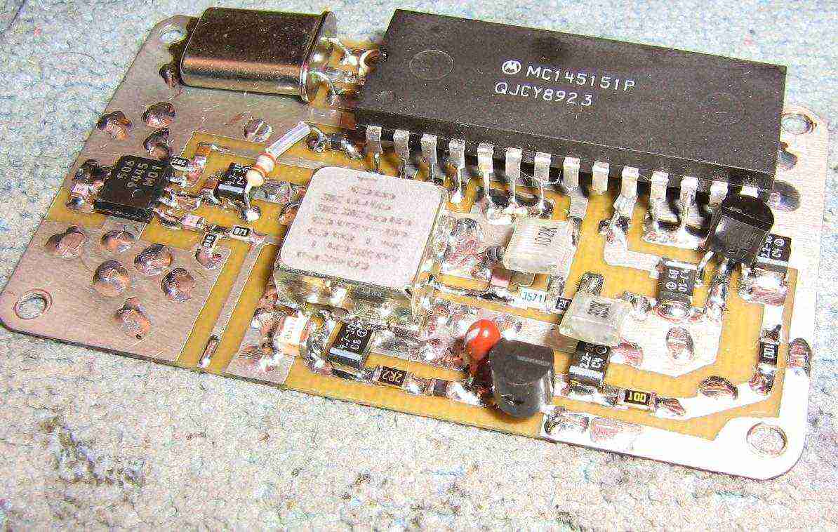
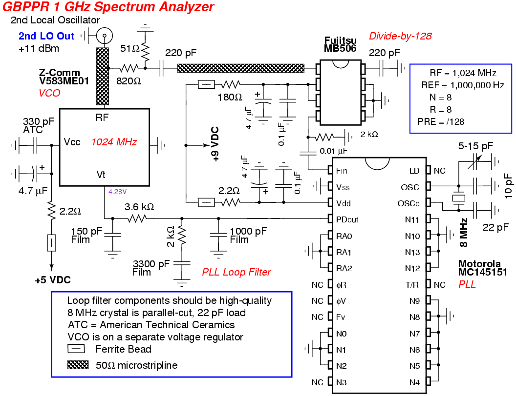
Second local oscillator circuit.
Phase-Locked Loop (PLL) synthesizer controlling a Z-Comm V583ME01 VCO at 1024 MHz. The PLL is based around a Motorola MC145151 synthesizer and a Fujitsu MB506 "divide-by-128" prescaler. The PLL reference frequency of 1 MHz is derived from a 8 MHz crystal.
The VCO is run off a separate low-noise +5 VDC regulator. The MC145151 is run at +9 VDC, as the final tuning voltage (apprx. +4.3V) for the VCO is a little too close to +5 VDC supply and there should be some overhead.
Use film capacitors and 1% metal-film resistors in the PLL loop filter section to avoid microphonics.
A variable capacitor is part of the loading on the 8 MHz reference crystal for slightly tweaking the final output frequency.
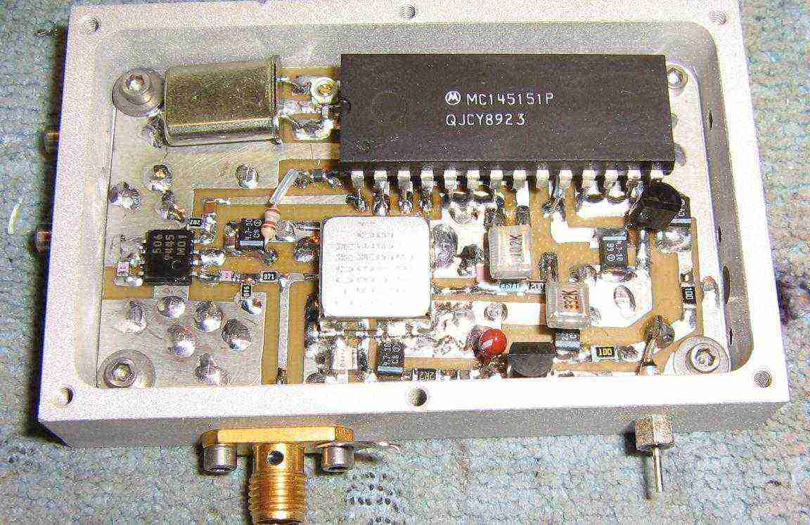
Finished second local oscillator.
RF power output is around +11 dBm, which is a little low for this application, but will still work.
The bottom SMA connector is for the Second Local Oscillator output.
This 1024 MHz local oscillator signal will feed the LO port on the second mixer.
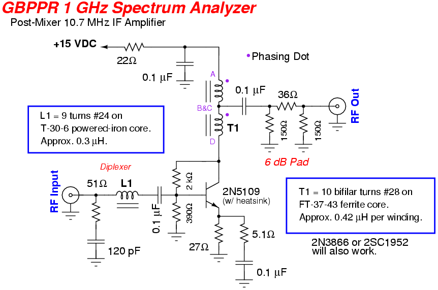
Post-mixer 10.7 MHz amplifier.
Stock circuit from the original W7ZOI/K7TAU project which provides a high-dynamic range post-mixer 10.7 MHz IF amplifier. This helps to recover some of the power lossed through the two mixers and bandpass cavity. It also provides the first bit of final filtering via the low-pass diplexer circuit.
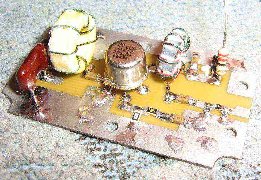
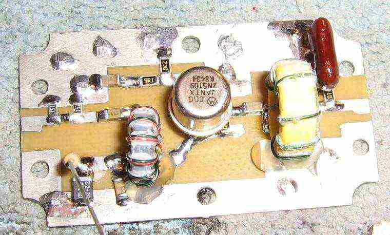
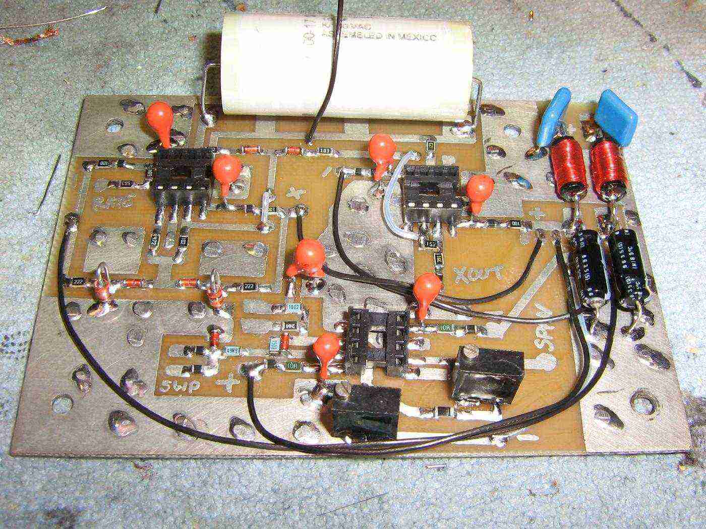
Post-mixer 10.7 MHz amplifier - alternate view.
The yellow toroid is approximately 0.3 µH and consists of nine turns of #24 enameled magnet wire on a T-30-6 powered-iorn core. That's a T-50-6 core in the picture, but there's a bit of leeway here.
A 6 dB resistive attenuator pad helps to maintain a 50 ohm output impedance and tames the high-impedance of the resolution filters down line.
The other toroid forms a 4:1 matching transformer to convert the 200 ohm output impedance of the 2N5109 down to 50 ohms. It consists of ten bifilar (twisted together) turns of #28 enameled magnet wire on a FT-37-43 ferrite core. Each winding measured around 0.42 µH. Be sure to keep track of the phasing when winding the core.
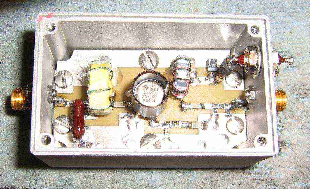
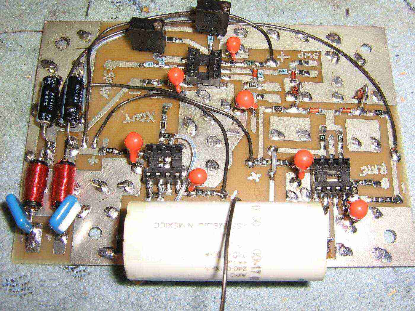
Finished post-mixer 10.7 MHz amplifier. Gain is around +17 dB at 10.7 MHz.
It's housed in an old 900 MHz preamplifer case and the 2N5109 should have a heatsink.
The RF input is from the IF port of the second mixer.

Bifilar-Wound Toroid
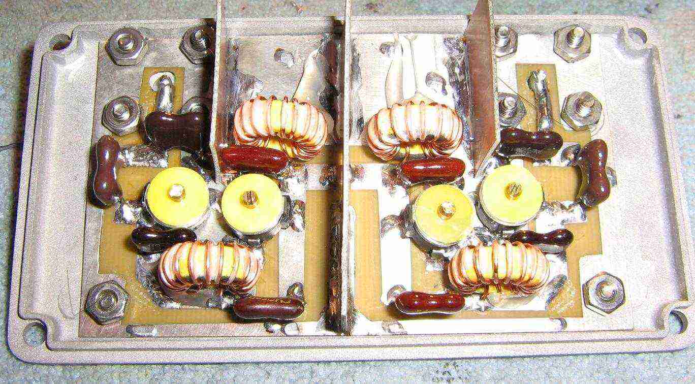
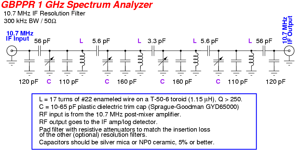
10.7 MHz IF resolution filter with a 3 dB bandwidth of 300 kHz and an insertion loss of around 4 dB.
This is also a stock circuit from the original W7ZOI/K7TAU project, with a few minor tweaks of capacitor values to tune up from 10 MHz to 10.7 MHz.
Try to keep the toroids at right-angles or well-shielded for maximum isolation. Capacitors are all silver mica, except for the 3.3 pF cap which is ceramic surface-mount.
This circuit is built onto the lid of a salvaged Bud CU-124 case for ease of removal for modification or tuning.
You'll need a 10.7 MHz signal generator and RF power meter (or diode detector or tracking generator) to properly tune the filter.
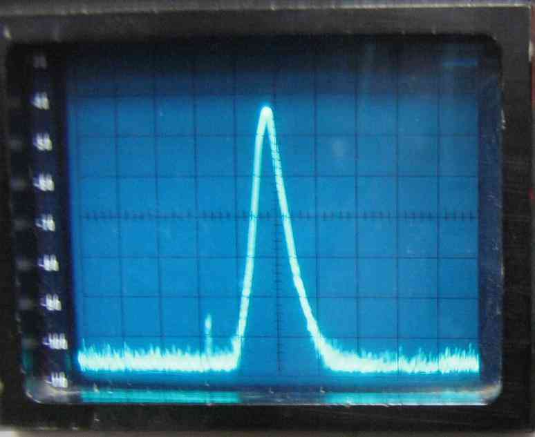
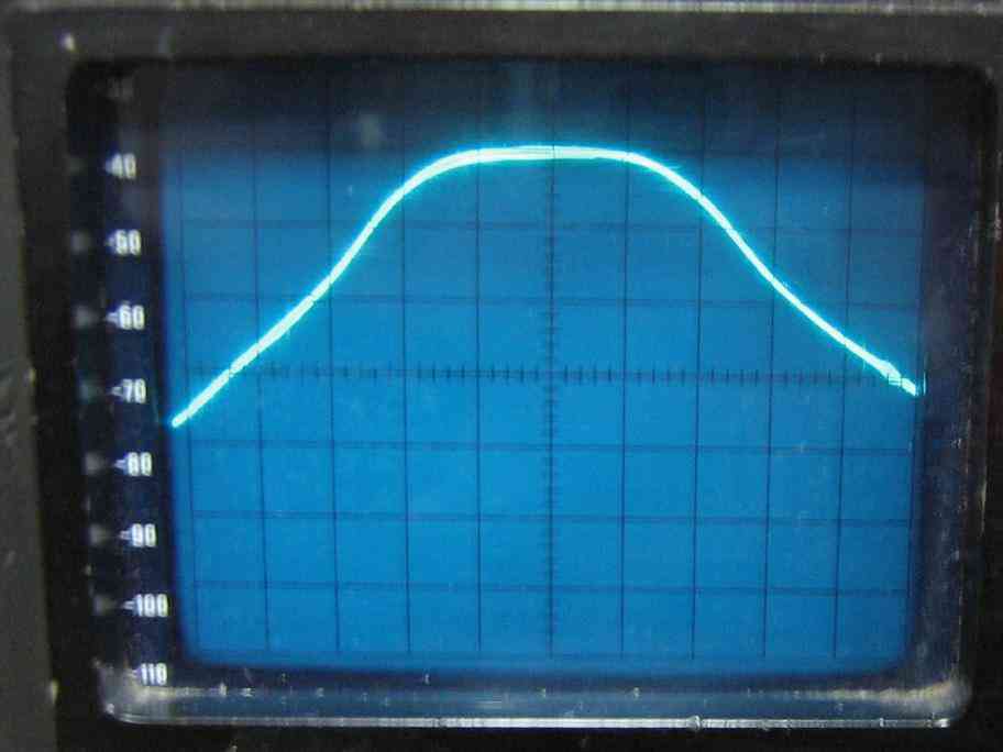
On the left, is a tracking generator sweep of this filter without any tuning (ignore the spur on the lower-left). The span is 1 MHz per horizontal division and 10 dB per vertical division. Note that it's a few hundred kilohertz off frequency and the insertion loss is kinda high. On the right is the spectrum view after proper tuning of the four capacitors. This view is 100 kHz per division. (Video)
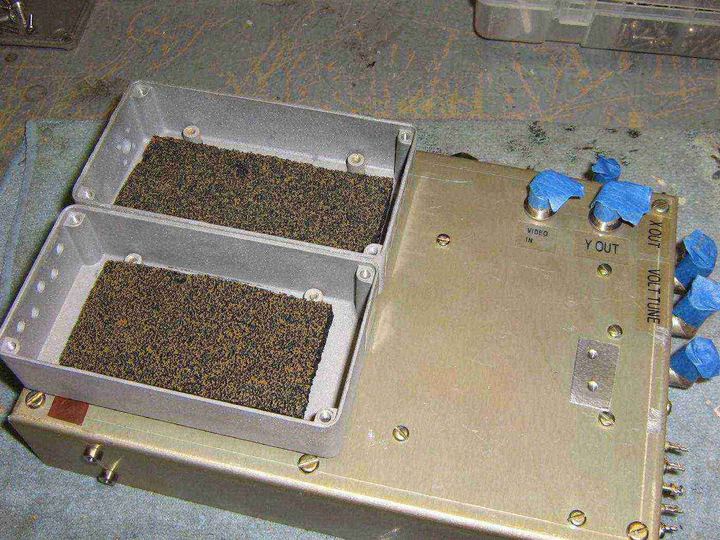
The 300 kHz (and future 30 kHz) resolution filters are fitted in separate cases for maximum isolation.
These are in turn attached to the case the sweeping generator and synchronization circuits will be housed in.
A few pieces of (optional) microwave absorbing foam knock down any resonances in the resolution filter cases.
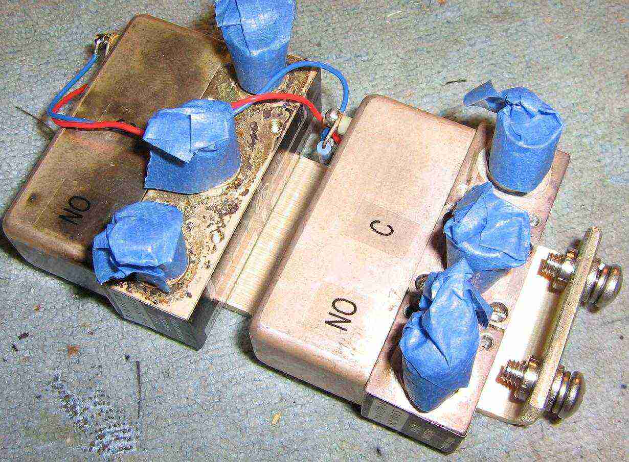
High-quality RF switches will be used to switch between the 300 kHz and 30 kHz resolution filters.
This will provide maximum isolation while still making it easy to remove the resolution filters for tuning.
These Dynaform 360 RF switches require +28 volts for switching. We'll "fake" this by connecting their negative terminals to -15 volts and switching +12 volts to their postive terminals.
When facing up, the center TNC connector is common, the left TNC connector is Normally Open (NO), and the right is Normally Closed (NC).
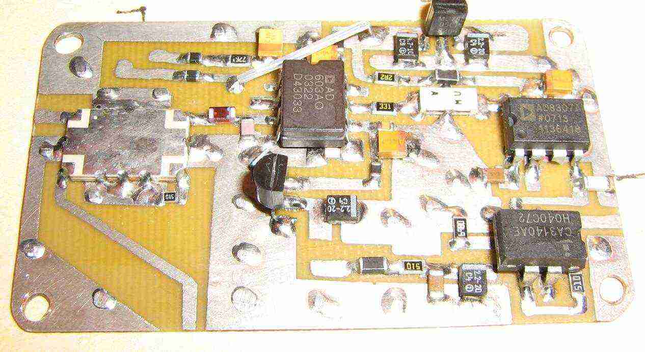
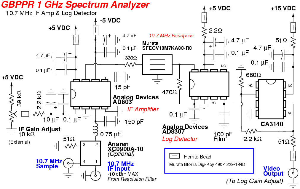
10.7 MHz IF amplifier, logarithmic detector, and video driver circuit.
The 10.7 MHz input (from the resolution filter) is on the left. It passes through an optional directional coupler to sample the 10.7 MHz IF for future FM demodulation purposes. A simple series inductor / shunt capacitor network matches the 50 ohm input to the 100 ohm input impedance of the Analog Devices AD603. An external 10k ohm potentiometer varies the gain of the AD603 IF amplifier from +10 to +50 dB. The output of the AD603 passes through a Murata SFECV10M7KA00-R0 10.7 MHz ceramic IF filter with a 110 kHz bandwidth (Digi-Key 490-1229-1-ND) to knock down spurious RF images that passed through from the resolution filters.
The logarithmic detector is based around the infamous Analog Devices AD8307 and the video driver is a CA3140 op-amp.
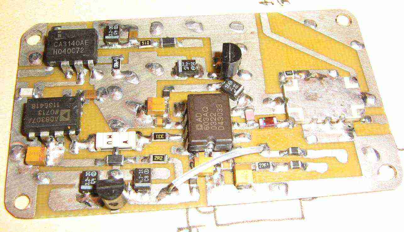
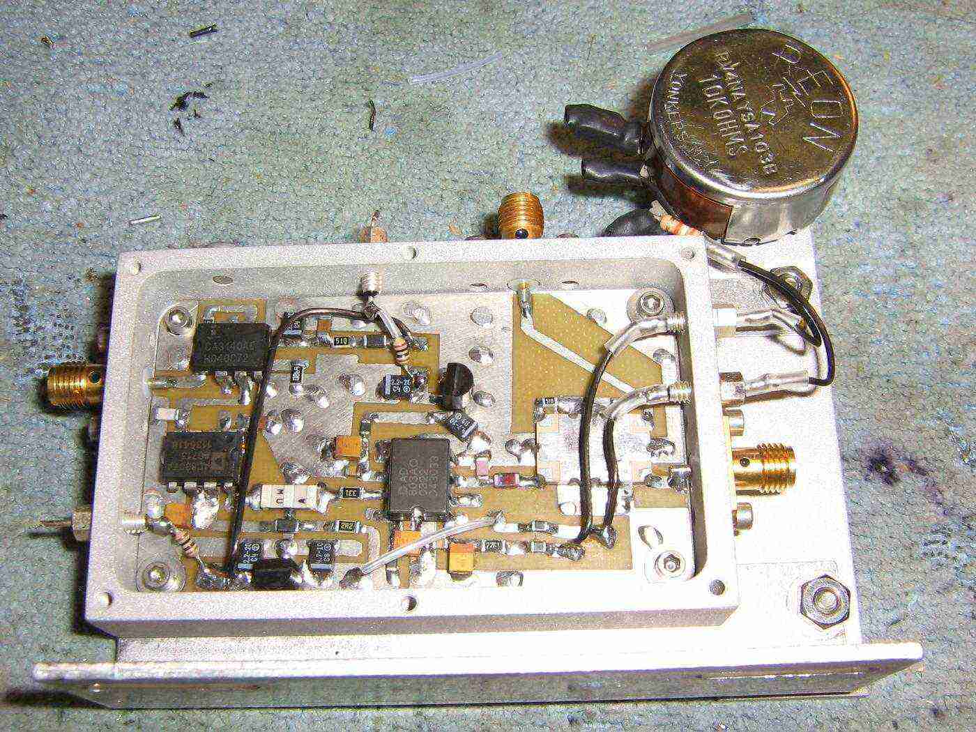
10.7 MHz IF amplifier, logarithmic detector, and video driver circuit - alternate view.
This circuit is based on the IF amp/log detector in the "Updates" PDF file on W7ZOI's website and in Experimental Methods in RF Design.
The AD603 is run at +/- 5 VDC instead of a single supply, as the AD603 can be unstable in that mode and this also eliminates alot of external components.
The Anaren XC0900A-10 directional coupler is actually designed for the 800 MHz cellular band, but it works fine for just picking off the incoming 10.7 MHz IF. This sample can then be sent to an external FM demodulator or to other signal processing circuits.
The IF Gain Adjust 10k ohm potentiometer is mounted externally on a little bracket.
This provides the 0-1 volt tuning voltage the AD603 requires. The control and power lines go to the potentiometer via 1000 pF feed-through capacitors.
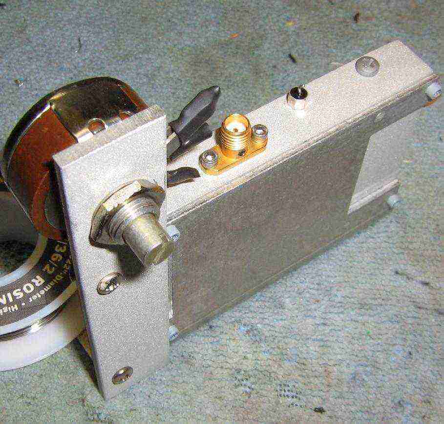
Finished 10.7 MHz IF amplifier, logarithmic detector, and video driver circuit overview.
+15 VDC input is via the lower-left feed-through capacitor.
-15 VDC input is via the top-center feed-through capacitor.
The SMA connector on the left is for the Video Output.
The SMA connector on the top-center is for the (optional) 10.7 MHz Sample.
The SMA connector on the right is for the 10.7 MHz IF Input.
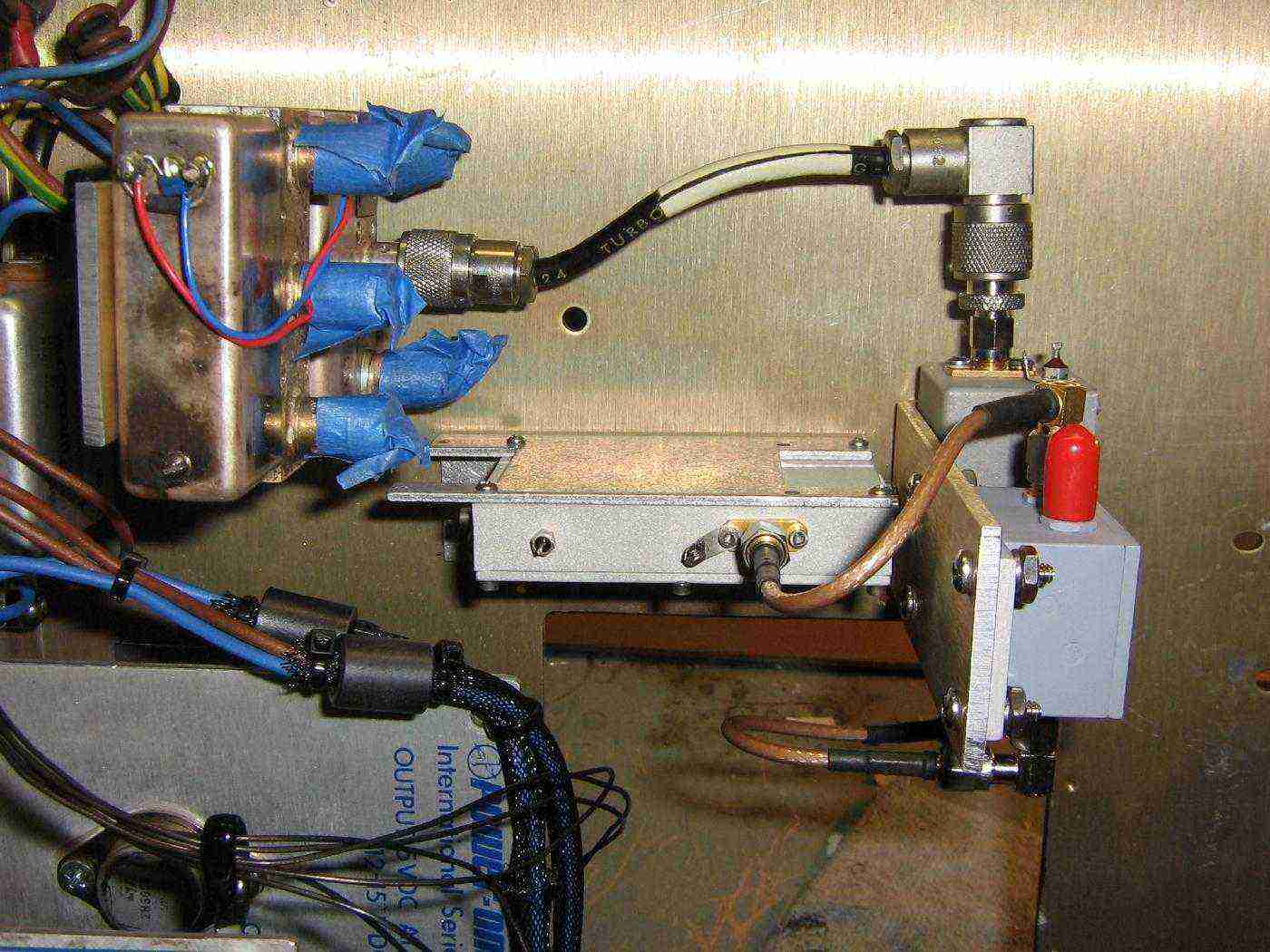
Completed left-panel of the spectrum analyzer.
Low-pass filter is on the lower-left feeding the IF port on the first mixer.
A large 4,600 µF electrolytic capacitor is mounted near the first local oscillator module and will serve as a "single point" for distributing the +15 VDC and ground signals to the other modules.
There is a Mini-Circuits SAT-3 3 dB attenuator on the RF port of the first mixer. This is to help the first mixer "see" 50 ohms on all ports and to isolate any impedance mismatch with the 1013.3 MHz bandpass cavity filter.
Overview of the second mixer and the post-mixer 10.7 MHz IF amplifier.
They are both mounted on a L-bracket.
Overview of the second mixer in position.
The 1024 MHz second local oscillator module is mounted behind it.
The output from the post-mixer 10.7 MHz IF amplifier module goes to the common port on the bottom RF switch.
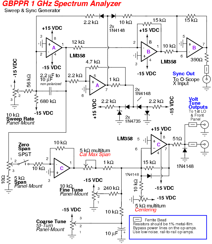
Overview of the sweep generator and synchronization circuit.
This is also a stock circuit from the original W7ZOI/K7TAU project, with a few minor tweaks.
The 1 µF non-polarized capacitor was increased in order to slow the sweep rate down a bit. This is so when using a narrow resolution filter the signal doesn't "sweep" through the filter faster than it can be displayed.
The original LM358 op-amps were also replaced with rail-to-rail, low-noise equivalents (LTC1047, etc.). All op-amps have 10 µF bypass caps and series 10 ohm resistors and a ferrite bead on their power lines. These are not shown in the schematic.
Alternate view of the sweep generator and synchronization circuit.
The large tubular object is a non-polarized 10 µF capacitor.
The two multiturn potentiometers are for centering and the maximum span calibration.
Try to use all 1% metal-film resistors in this circuit.
This circuit has two sweep outputs, one of which goes to the front-panel. This is handy for just using the sweep generator's ramp signal to sweep an external VCO and diode detector combination when tuning filters. The sweep outputs should be well-shielded.
Installation of the sweep generator and synchronization circuit into its own project box.
The 5k ohm potentiometer on the top for Log Gain Adjust. The 0.01 µF capacitor from the wiper terminal is for an optional video filter to be switched in to clean up the final spectrum display.
This particular box had a number of feed through capacitors which will be ideal for passing the tuning signals in and out. BNC connectors will be used for the sweep and X/Y outputs.
An optional 10.7 MHz IF input BNC jack was added for future projects.
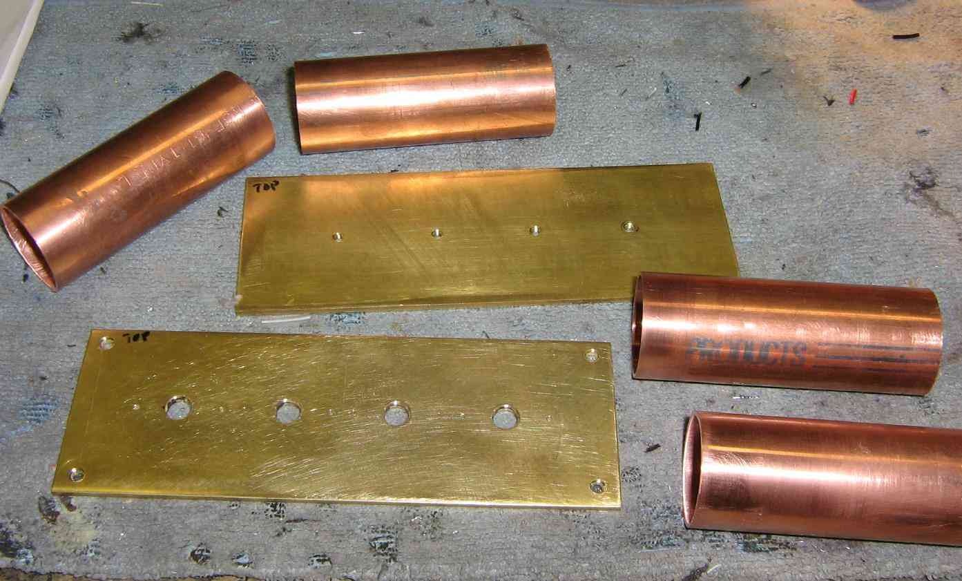
Constructing the 1013.3 MHz first IF cavity bandpass filter.
Shown are 1-inch diameter copper pipe and some K&S Metals 0.093-inch brass plate stock.
This filter design is straight from Scotty's spectrum analyzer project. View his detailed construction and layout notes at: scottyspectrumanalyzer.com/cavity.html
The main purpose of this filter is to attenuate the image frequency of 1034.7 MHz and the second LO frequency of 1024 MHz. When properly constructed, this filter should attenuate those two frequencies by at least 80 dB.
There was one problem with the filter shown here. Mine didn't work! My mechanical construction skills are not quite that good, so that was probably part of the problem. You'll need to follow Scotty Sprowls' instructions and dimensions exactly, or yours won't work either. Several people have gotten this same cavity filter to work, so the instructions and design are sound.
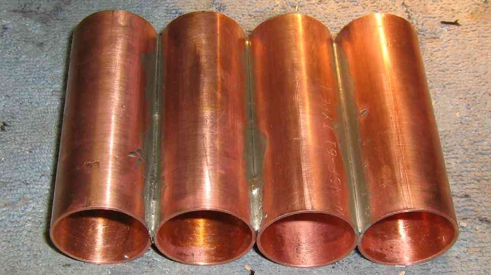
Cut the 1-inch diameter copper pipe to 3.1-inch lengths and solder them together.
Try to use silver-solder as the high melting temperature will be handy for when you need to solder the other connections using regular solder.
Clean the copper pipe with emory cloth and use solder flux paste on areas for solder to flow. You'll need to clamp the pipes together somehow for soldering. Use some ingenuity here!
Use a belt sander to make them all even when finished.
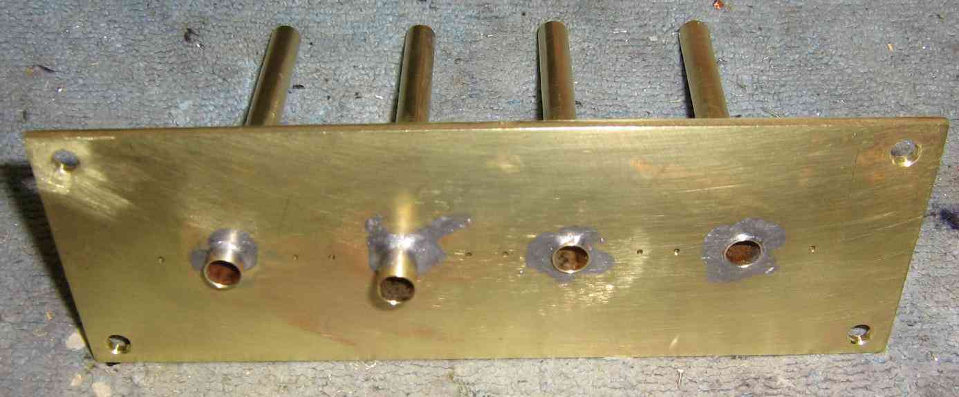
Solder the four main tuning stubs.
1/4-inch diameter brass tube was used here. Copper would give better RF performance.
Drill the holes in the base plate a little smaller than 1/4 inch (15/64), then use a reamer to widen them. Pass the tuning stubs through these holes so they are 2.72 inches above the brass plate. The friction should hold the brass stubs in place while you solder them.

Tuning stubs soldered.
Try not to get too much solder on top of the brass plate. This can effect the final tuning of the cavity.
Installing the coupling loops 0.7-inches above the bottom brass plate.
They are made from the center conductor and Teflon insulation from scrap pieces of UT-141 hardline coax.
The spacing from the copper pipe is very critical and I think that's why my version didn't work.
Each of these coupling loops should be the same distance (0.06-inch) from the edge of the copper pipe.
Installing the input and output probes.
These are also scrap pieces of UT-141 hardline coax but with SMA connectors installed.

Coupling loops in place.
Top overview.
Be sure the tuning stubs are centered in the copper pipe.

Assembled 1013.3 MHz cavity bandpass filter - that didn't work!
The filter's insertion loss will be around 8 dB and the 3 dB bandwidth around 2 MHz if all the coupling loops are the proper distance from the side of the copper pipe. Lower insertion loss means the filter's 3 dB bandwidth might be a little too large and won't properly attenuate the image signal.
I used some pieces of #8-32 threaded rod to hold the top plate on to ease soldering. This also makes a handy mounting point for the filter.
Four brass #4 screws (3/4-inch long) are for tuning the filter. The holes were tapped for #4-40. Add locking jam nuts to the brass screws when then the filter is finally tuned.
Tune the filter using the RF output from the first local oscillator as a signal generator and a diode detector (or RF power meter).
Update! I made a new 1013.3 MHz Cavity Filter using a commercial Celwave 800/900 MHz mobile duplexer.