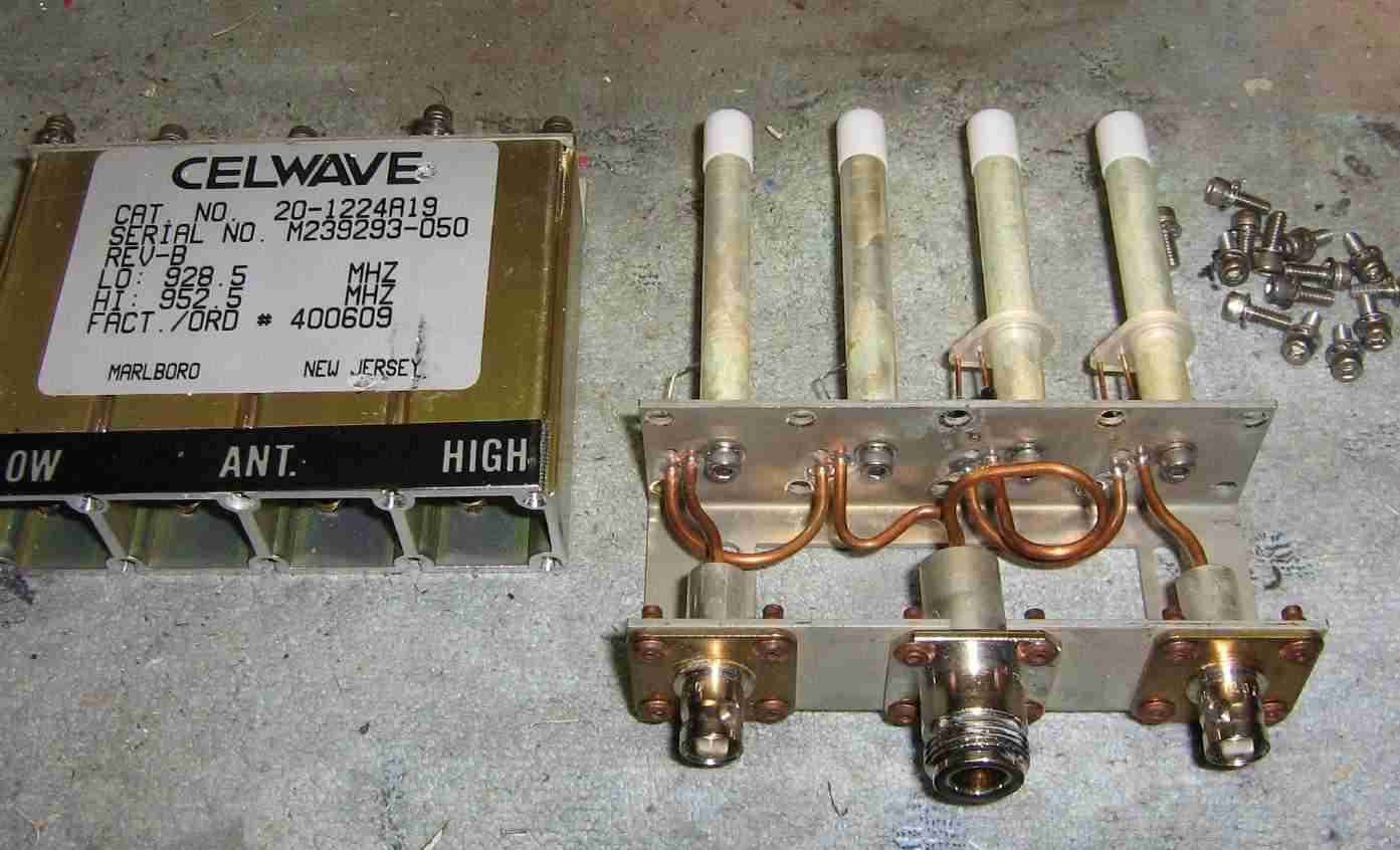
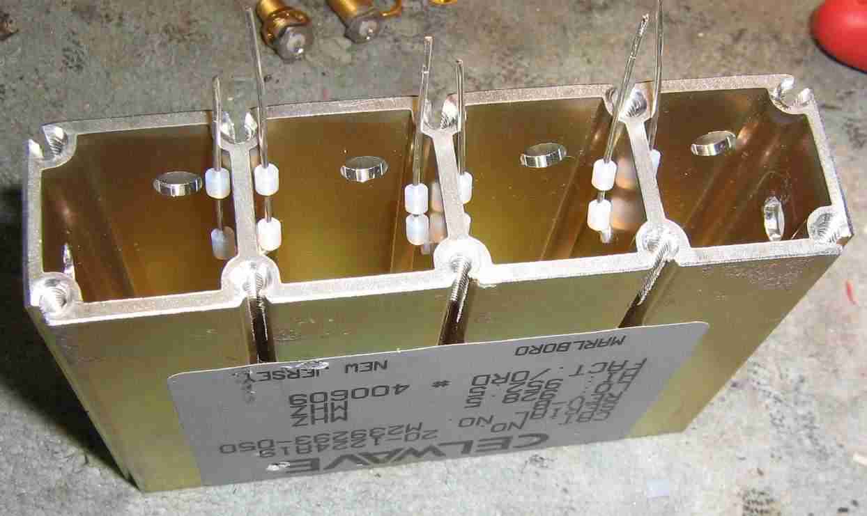
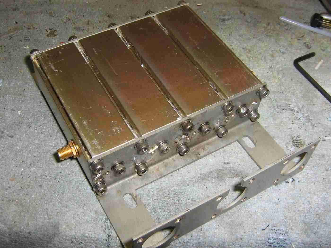
Stock Celwave Model No. 20-1224A19 duplexer internal view.
The stock RF connectors and bits of hardline coax will need to be removed. The connectors are rivoted to the base assembly, so you'll have to drill those out. Use a heat gun to heat the pieces of hardline coax and they'll slip right out.

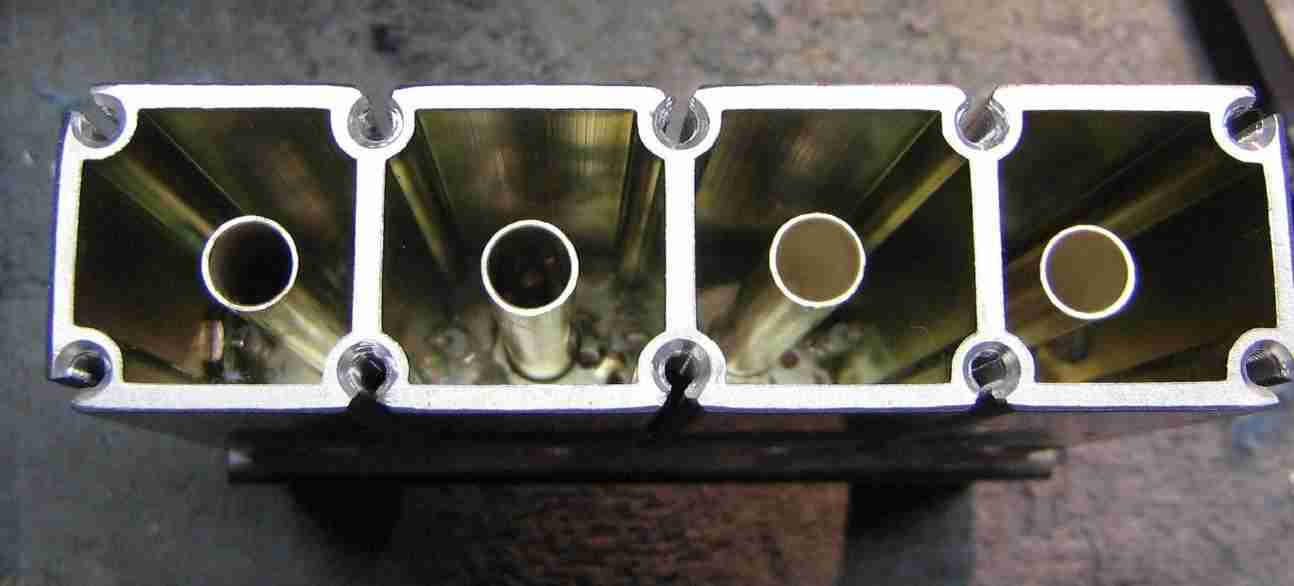
Closeup of the four main tuning posts inside the duplexer.
They are 2.5 inches long and 0.34 inches in diameter. Four stainless steel #6-32 screws hold each of the posts to the main base assembly.
The duplexer's stock coupling loops will need to be unsolder or trimmed off of the tuning posts, as they will not be used here. Be sure not to loose the little white Teflon caps on each of the posts.
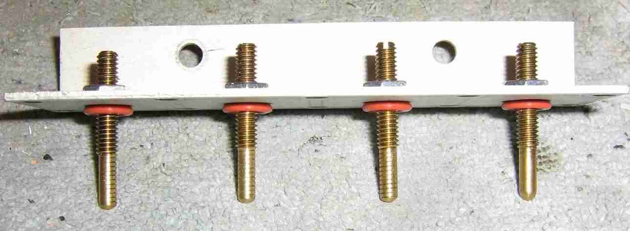
Top plate of the duplexer showing the four brass tuning screws which fit inside the Teflon caps on the tuning posts.
This will require no modification.
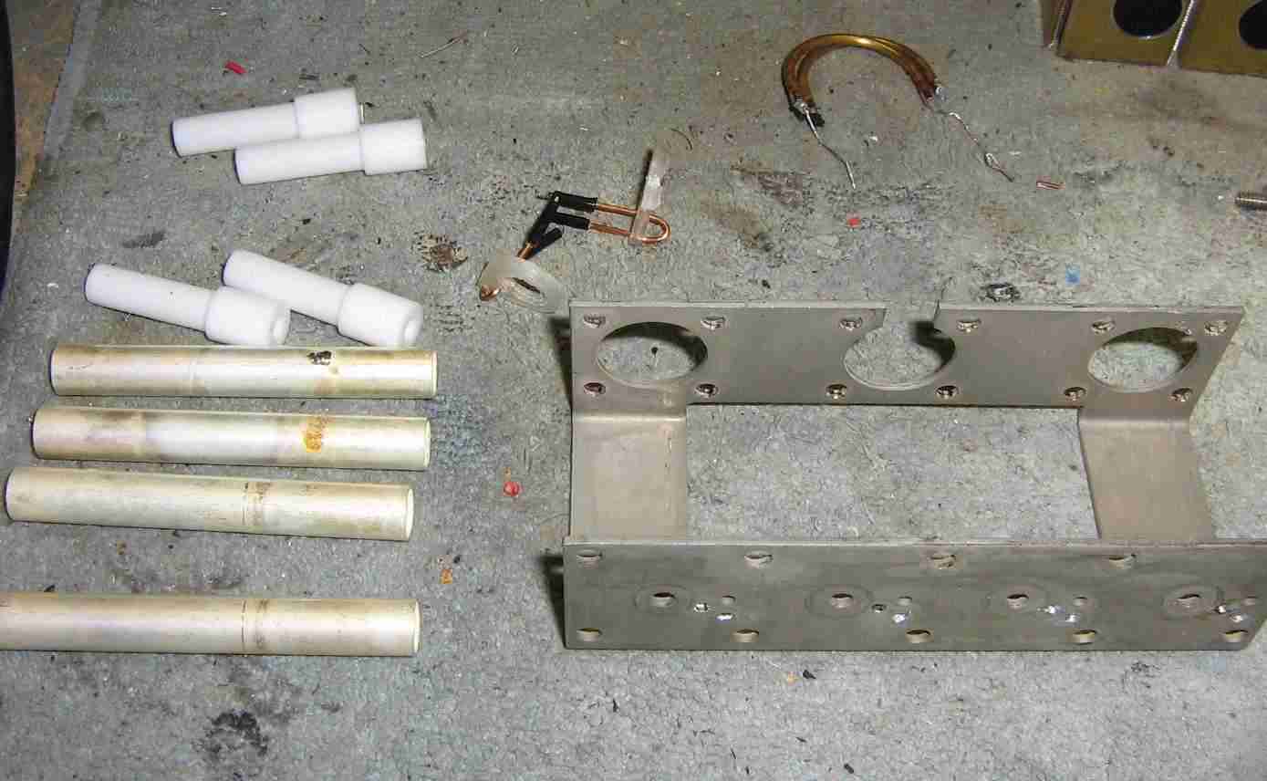
Taking the duplexer apart.
Be sure not to damage the silver plating on the main tuning posts.
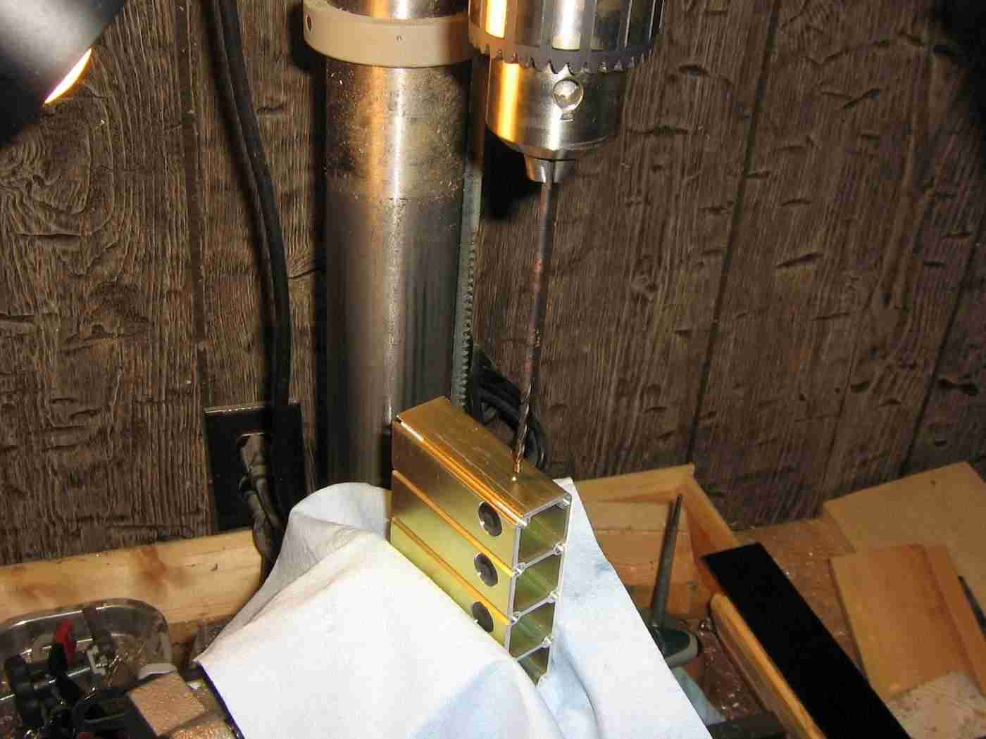
Drilling a 1/8 inch hole through the four cavitys for the new coupling loops.
The hole is 0.7 inches from the base, as per the original filter design.
Using a 1/8 inch hole held the bits of Teflon dielectric from the UT-141 hardline coax a little better.
Be sure the drill bit doesn't wander as it passes through the side of each cavity.

The duplexer's base assembly.
You should mark the internal sides of cavity with a scriber before disassembling the duplexer.
Note that there are three small holes near where the tuning post attached. Only two of these holes were used originally, and we'll be using the unused hole for the new coupling loops.
Drill four #56 sized holes 0.06 inches from the inside of the cavity which you marked with a scribe. This will be for the new coupling loops on the otherside of the cavity.
Construct the internal coupling loops from bits of scrap UT-141 hardline coax as per the original cavity filter design.
This will be much easier to do since the sides of the cavity are square.
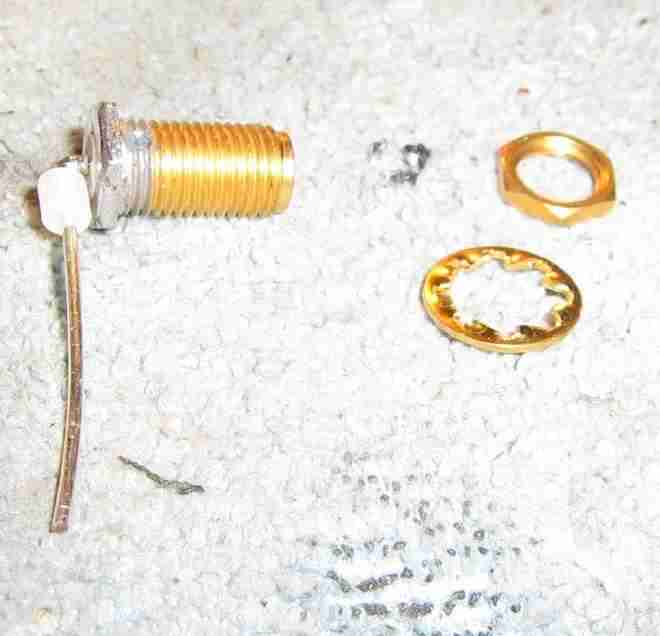
Since the duplexer's cavity is made from aluminum, we won't be able to solder the input and output connections like in the original cavity filter design.
To overcome this, we'll be using panel-mount SMA jacks with pigtails made from scraps of UT-141 coax.
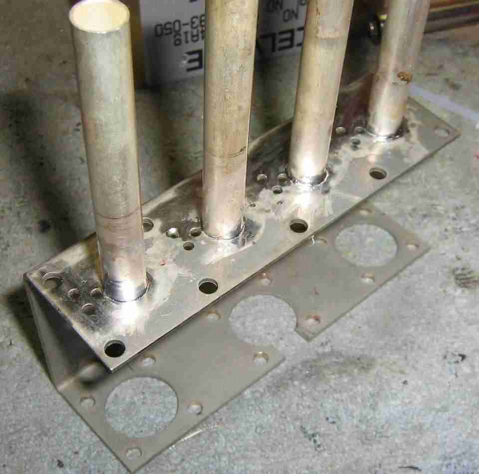
Soldering the main tuning stubs to the base assembly.
The stock duplexer held the main tuning stubs using only screws. Since this connection is fairly critical, we'll add a bit of silver solder to the base of the tuning stubs to prevent them from coming loose.
This is optional, but probably very helpful.
Putting everything back together.
Since the cavity is held together using screws, you can easily take it apart and tweak the coupling loop spacing.
Add a bit of Loctite to the screws to help secure the final filter design.

Bottom of the base assembly showing the solder connections.
A few solder "blobs" cover up those unused holes.
You'll have to solder quickly to prevent the solder connection on the SMA connectors from coming undone.

The duplexer originally had solder access holes in the sides of the cavity. They are plugged using a rubber stopper.
We'll use these access holes to add a dab of Remington MoistureGuard grease into each cavity. When this grease evaporates, it coats the sides of the cavity to prevent any oxidation from taking place.
You can find Remington MoistureGuard at most gun stores.
Final 1013.3 MHz bandpass cavity filter overview.
I don't have a spectrum sweep of the bandpass response, but it does appear to work or at least is a very good starting point.
The filter in symmetrical, so either SMA jack can be used for the RF input or output.