The stock radio uses a TXCO which suffers from drift over time and temperature. The frequency drift can be 10 - 30Hz which is not huge - but can make a noticeable difference when working CW or ESSB. Alan K2WS explains the reasons why accuarcy is critical - part of his web info reads;
"Alan Davis K2WS
February 3, 2006
My SDR’s frequency
stability needed some improvement. These days has been ESSB or High quality
SSB. Using these modes, it is important that the rig be absolutely stable
because a change of 10 to 30Hz will spoil an otherwise excellent quality signal.
I did a study on the effect of changes in temperature in the SDR
cabinet with changes in frequency. I found on my rig that the oscillator
drifted (@ 15mHz) about 5Hz/ F° and that SSB transmissions would increase the
internal cabinet temperature as much as 5° to 10° F. This resulted in a
see-saw, up-down frequency drift of 10 to 25Hz during a QSO! The only time the
rig was stable was during receive only mode and only when the room temperature
didn't change more then 1° F.
While 25Hz ‘drift’ might not even
be noticeable for everyday SSB/CW operation, I required more stability for my
ESSB operation. I suspect there are many other SDR users who also require
higher stability such as VHF,UHF, microwave users and data mode users."
Alan has also produced an interesting PDF document where he has graphed
the frequency drift as affected by time / temperature. You can have a
read of this document by clicking here. Many thanks to Alan for his kind permission to reproduce the information on my site.
In September 2007 I ordered an external frequency reference kit and installed it using a 10MHz Rubidium source. I sourced the Rubidium via ebay, which is from Tait Telecoms equipment. The Rubidium module has an output amplitude of +8dbm with a 10MHz frequency. The Flexradio installation of the kit, whilst straightforward, is not for the faint hearted. Within a few minutes of commencing the modification, my SDR was in bits.... The following pictures may give you an idea of whats entailed.

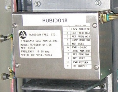
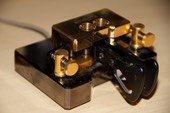
These pictures show the Tait box that I picked up from ebay, and then a close-up of the actual Rubidium 10MHz source. The Tait box already had a 24V supply, so at the moment I am using the whole box. At a later date I may remove the source and power supply and re-fit them in a smaller enclosure.
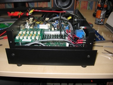

The picture above left shows the SDR with the bandpass filter and RXE board fitted in place, the picture on the right shows the radio with these boards removed.


The BPF and RXE boards


The factory fitted oscillator on the left and the TRX board on the right with it removed.

This last picture shows the socket with a small piece of RG174 fitted which leads to the BNC socket on the back of the radio facilitating the external frequency source. The kit received direct from Flexradio had a piece of coax that was about 4 inches long, I found this too short and used my own. You can also see the shunts moved to pins 2 & 3.

Don't forget to adjust the PLL multiplier - you need to be in expert mode to change it.
The
end
result is brilliant, with a completely stable and accurate frequency - no drift!
My clock-off set is set to zero! At this time I took the opportunity to
conduct some station tests checking the frequency accuracy of my radio
- I used my Icom IC7000, two dummy loads, a bench frequency counter and
my 100MHz CRO. My SDR is 'spot-on'. Prior to undertaking this
modification I had a good read of the Flexradio site and also had a
good look at the excellent SDR web pages of
.
Page last updated 10/12/2007