| |
MODULE V - FUNDAMENTALS OF ELECTRONICS
RESISTORS
This Chapter describes fixed value resistors and outlines some of the
important uses of resistors in electronic circuits.
What do resistors do?
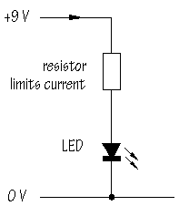
Resistors limit current. In a typical application, a resistor is connected in series
with a Light Emitting Diode (LED):
 |
 |
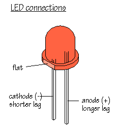
Enough current flows to make the LED light up, but not so much that the LED is damaged. Later in this Chapter, you will find out how to calculate a suitable value for this resistor. (LEDs are described in detail in Chapter 5.)
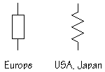
The 'box' symbol for a fixed resistor is popular in the UK and Europe. A 'zig-zag'
symbol is used in America and Japan:

Resistors are used with transducers to make sensor subsystems.
Transducers are electronic components which convert energy from one form into another,
where one of the forms of energy is electrical. A light dependent resistor,
or LDR, is an example of an input transducer. Changes in
the brightness of the light shining onto the surface of the LDR result in changes in its
resistance. As will be explained later, an input transducer is most often connected along
with a resistor to to make a circuit called a potential divider. In this
case, the output of the potential divider will be a voltage signal which reflects changes
in illumination.
Microphones and switches are input transducers. Output transducers
include loudspeakers, filament lamps and LEDs. Can you think of other examples of
transducers of each type?
In other circuits, resistors are used to direct current flow to particular parts of the
circuit, or may be used to determine the voltage gain of an amplifier. Resistors are used
with capacitors to introduce time delays.
Most electronic circuits require resistors to make them work properly
and it is obviously important to find out something about the different types of resistor
available, and to be able to choose the correct resistor value, in  , ,  , or M , or M , for a particular
application. , for a particular
application.
Fixed value resistors
The diagram shows the construction of a carbon film resistor:

During manufacture, a thin film of carbon is deposited onto a small ceramic rod. The
resistive coating is spiralled away in an automatic machine until the resistance between
the two ends of the rod is as close as possible to the correct value. Metal leads and end
caps are added, the resistor is covered with an insulating coating and finally painted
with coloured bands to indicate the resistor value.
Carbon film resistors are cheap and easily available, with values within �10% or �5%
of their marked, or 'nominal' value. Metal film and metal oxide
resistors are made in a similar way, but can be made more accurately to within �2% or
�1% of their nominal value. There are some differences in performance between these
resistor types, but none which affect their use in simple circuits.
Wirewound resistors are made by winding thin wire onto a ceramic rod.
They can be made extremely accurately for use in multimeters, oscilloscopes and other
measuring equipment. Some types of wirewound resistors can pass large currents wihtout
overheating and are used in power supplies and other high current circuits.
Colour code
How can the value of a resistor be worked out from the colours of the bands? Each
colour represents a number according to the following scheme:
| Number |
Colour |
| 0 |
black |
| 1 |
brown |
| 2 |
red |
| 3 |
orange |
| 4 |
yellow |
| 5 |
green |
| 6 |
blue |
| 7 |
violet |
| 8 |
grey |
| 9 |
white |
The first band on a resistor is interpreted as the FIRST DIGIT of the resistor value.
For the resistor shown below, the first band is yellow, so the first digit is 4:

The second band gives the SECOND DIGIT. This is a violet band, making the second digit
7. The third band is called the MULTIPLIER and is not interpreted in quite the same way.
The multiplier tells you how many noughts you should write after the digits you already
have. A red band tells you to add 2 noughts. The value of this resistor is therefore
4 7 0 0 ohms, that is, 4 700  , or 4.7 , or 4.7  . Work through
this example again to confirm that you understand how to apply the colour code given by
the first three bands. . Work through
this example again to confirm that you understand how to apply the colour code given by
the first three bands.
The remaining band is called the TOLERANCE band. This indicates the percentage accuracy
of the resistor value. Most carbon film resistors have a gold-coloured tolerance band,
indicating that the actual resistance value is with + or - 5% of the nominal value. Other
tolerance colours are:
| Tolerance |
Colour |
| �1% |
brown |
| �2% |
red |
| �5% |
gold |
| �10% |
silver |
When you want to read off a resistor value, look for the tolerance
band, usually gold, and hold the resistor with the tolerance band at its right hand end.
Reading resistor values quickly and accurately isn't difficult, but it does take practice!
More about colour codes
The colour code as explained above allows you to interpret the values of any resistor
from 100  upwards. How does the code work
for values less than 100 upwards. How does the code work
for values less than 100  ? Here is the
code for 12 ? Here is the
code for 12  : :
brown red black
The multiplier colour black represents the number 0 and tells you that no
noughts should be added to the first two digits, representing 1 and 2.
What would be the colour code for 47  ?
The answer is: ?
The answer is:
yellow violet black
Using this method for indicating values between 10  and 100 and 100  means that all
resistor values require the same number of bands. means that all
resistor values require the same number of bands.
For values bewteen 1  and 10 and 10  , the multiplier colour is changed to gold.
For example, the colours: , the multiplier colour is changed to gold.
For example, the colours:
brown black gold
indicate a 1  resistor, while the
colours: resistor, while the
colours:
red red gold
refer to a 2.2  resistor. resistor.
Metal film resistors, manufactured to 1 or 2% tolerance, often use a code consisting of
four coloured bands instead of three. The code works in the same way, with the
first three bands interpreted as digits and the fourth band as the multiplier. For
example, a 1  metal film resistor has
the bands: metal film resistor has
the bands:
brown black black brown (+brown or red for tolerance)
while a 56  metal film resistor has
the bands: metal film resistor has
the bands:
green blue black red
It is worth pointing out that the multiplier for metal film resistors with values from
1  upwards is brown (rather than red, as
in the three colour system), while the multiplier for 10 upwards is brown (rather than red, as
in the three colour system), while the multiplier for 10  upwards is red (instead of orange). upwards is red (instead of orange).
You are likely to use low value resistors and metal film resistors on
some occasions and it is useful to know how to read their codes. However, most of the
resistors you use in building electronic circuits will be carbon film types with values
indicated using the three band colour code. It is this system which you should master
first.
Free download Color Code Convertor Program.
More on Resistors >>>
|