|
ONLINE MORSE CODE QUIZ/TEST |
|
Preparing for the Morse Code Test? Try our online Morse Code Quiz/Test and test your speed!

|
|
CALL BOOK |
|
All Hams! Add Your Call Sign to our Call Book. Register Now!

|
|
BULLETIN BOARD |
|
Post your announcements, invitations, ham activities for all the world to see! Or open a topic for
discussion! And of course, have Fun!
|
|
PUBLIC PHOTO CENTER |
|
Upload your photos for public viewing! Ham radio activities and personal photos accepted!
|
|
GUEST MAP |
|
Pin your location on our Website Guest Map and leave your message!
|
Vote For This Site!

MEMBERS!
| |
MODULE V - FUNDAMENTALS OF ELECTRONICS
CAPACITANCE
What is capacitance?
In the topic current we learnt of the unit of measuring electrical quantity or charge was a coulomb. Now a capacitor (formerly condenser) has the ability to hold a charge of electrons.
The number of electrons it can hold under a given electrical pressure (voltage) is called its capacitance or capacity. Two metallic plates separated by a non-conducting substance between them make a simple capacitor. Here is the symbol of a capacitor in a pretty basic circuit charged by a battery.
Figure 1. - capacitor schematic in a circuit
In this circuit when the switch is open the capacitor has no charge upon it, when the switch is closed current flows because of the voltage pressure, this current is determined by the amount of resistance in the circuit. At the instance the switch closes the emf forces electrons into the top plate of the capacitor from the negative end of the battery and pulls others out of the bottom plate toward the positive end of the battery.
Two points need to be considered here. Firstly as the current flow progresses more electrons flow into the capacitor and a greater opposing emf is developed there to oppose further current flow, the difference between battery voltage and the voltage on the capacitor becomes less and less and current continues to decrease. When the capacitor voltage equals the the battery voltage no further current will flow.
The second point is if the capacitor is able to store one coulomb of charge at one volt it is said to have a capacitance of one Farad. This is a very large unit of measure. Power supply capacitors are often in the region of 4,700 uF or 4,700 / millionths of a Farad. Radio circuits often have capacitances down to 10 pF which is 10 / million, millionths of a Farad.
The unit uF stands for micro-farad (one millionth) and pF stands for pico-farad (one million, millionths). These are the two common values of capacitance you will encounter in electronics.
Time constant of capacitance
The time required for a capacitor to reach its charge is proportional to the capacitance value and the resistance value.
The time constant of a resistance - capacitance circuit is:
T = R X C
where T = time in seconds
where R = resistance in ohms
where C = capacitance in farads
The time in this formula is the time to acquire 63% of the voltage value of the source. It is also the discharge time if we were discharging the capacitance. Should the capacitance in the figure above be 4U7 (4.7 uF) and the resistance was 1M ohms (one meg-ohm or 1,000,000 ohms) then the time constant would be T = R X C = [1,000,000 X 0.000,0047] = 4.7 seconds. These properties are taken advantage of in crude non critical timing circuits.
Capacitors in series and parallel
Capacitors in parallel ADD together as C1 + C2 + C3 + ..... While capacitors in series REDUCE by:
1 / (1 / C1 + 1 / C2 + 1 / C3 + .....)
Consider three capacitors of 10, 22, and 47 uF respectively.
Added in parallel we get 10 + 22 + 47 = 79 uF. While in series we would get:
1 / (1 / 10 + 1 / 22 + 1 / 47) = 5.997 uF.
Note that the result is always LESS than the original lowest value.
Simplified calculations for Capacitors
We said above that parallel combinations simply add the values together. Series combinations are somewhat more difficult requiring 1 / (1 / C1 + 1 / C2 + 1 / C3 + ...).
This can be simplified somewhat to:
[(C1 X C2) / (C1 + C2)]
Try three or more in series. Do the first two then arrive at an intermediate value, then do the third with the intermediate value and so on.
What is even more difficult is if you need to use a series combination to get down from a known value capacitor to a desired net value of capacitance. In that case use this formula:
[(C1 X C2) / (C1 - C2)]
As one example, if you have a 220 pF fixed capacitor but need a net value of about 68 pF:
[(220 X 68) / (220 - 68)] = 98.4 pF (use 100 pF)
Again try three or more in series. Do the first two then arrive at an intermediate value, then do the third with the intermediate value and so on.
Remember low value capacitors are 5% tolerance and higher values are likely 10% so don't get too paranoid with precision calculations. As an exercise play around with 18 pF 5% tolerance and 82 pF 10% tolerance using both extreme ends of tolerance as well as their nominal values. Helps to keep things in perspective.
Figure 2. - capacitors in series and in parallel
A very important property of Capacitors
Capacitors will pass AC currents but not DC. Throughout electronic circuits this very important property is taken advantage of to pass ac or rf signals from one stage to another while blocking any DC component from the previous stage.
Figure 3 - capacitors passing ac blocking dc
What do capacitors look like?
In figure 4 we have a photo of a selection of fixed and variable capacitors. The upper capacitor is a variable capacitor. Down the left hand side we have a number of electolytic capacitors.
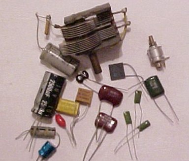
Figure 4 - a selection of fixed and variable capacitors
The red capacitor in the lower left is a tag tantalum type of greater tolerance and high stability. The yellow is a metallised polypropylene film type while the green ones at the right are the popular polyester types "Greencaps".
In the middle are silver mica capacitors which I personally think are somewhat over rated although these were 1% tolerance types. At the upper right is a 25 pF beehive trimmer.
|
