| Construction details | 9-Ele.-28-Ohm | 10-Ele-28-Ohm | 11-Ele-28-Ohm |
| 12-Ele.-28-Ohm | 14-Ele.-28-Ohm | 17-Ele.-28-Ohm | 19-Ele.-28-Ohm |
For the design principles of high-gain Longyagis click here
|
|
Latest versions, optimized for gain, pattern and SWR! Very important Informations for constructing, please read all carefully before assembling!
Meanwhile a lot of contest-crews are working with vertically stacked DK7ZB-Yagis. Easy to build, easy to match and good results.
The picture left shows the 4x9-Element with 18dBd gain
by Miros, OK1KRQ
|
The philosophy of the DK7ZB-Longyagis is:
High gain, good pattern and acceptable bandwidth. These aims can be realized with a radiation-resistance of 25-35Ohms. Because the 28-Ohm-feedpoint is very simple to match, I use this impedance for my long Yagis.
Russ (VA3RR/AA8LU) has a comparison of well know longboom Yagis on his homepage www.qsl.net/va3rr

The Yagis are in the VE7BQH-List, there you find the stacking dimensions for H-groups (mni tnx to Lionel, VE7BQH!). The Yagis are designed for the SSB/CW- and EME-part of the band, a very good SWR can be expected between 144,0 and 144,6MHz. The 9-el-Yagi is updated now and has higher gain and better G/T.
The feedpoint impedance for all Yagis is 28Ohm, the radiator is a simple split-dipole with the DK7ZB-match. Keep the length 2mm longer each side, the fine-tuning for best SWR is made by shortening the radiator to SWR-minimum. If you get an SWR > 1.2, there is something wrong!
The 2x75-Ohm-coax-cables for the match 28/50Ohm must be absolutely parallel. If you mount them above the boom, take a piece of isolated material (uncritical) of 2-3mm thickness between the cables and the boom.The high voltage at power >300W RF can cause a short circuit and arcing between screen and boom!
The given length of the radiator elements are from tip to tip, including 10mm spacing for the insulated part.
|
|
This professional dipole is constructed by DJ3MF. For hams he is willing to build some of these excellent radiators for the 28/50-Ohm match. To contact him use his e-mail adress:
|
|
These are the parts for the DJ3MF-radiator-box. The coax-socket will be grounded by the screw for fixing the radiator to the boom. |
|


![]()

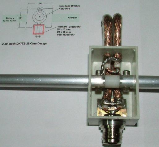
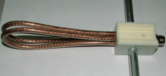
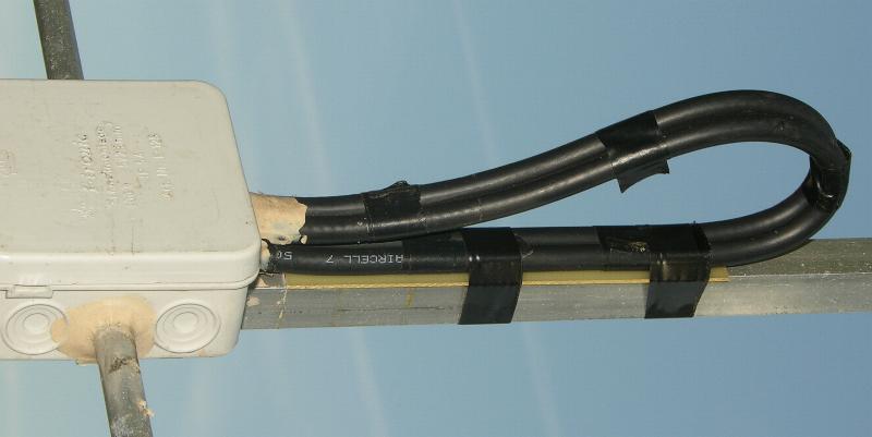
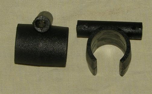
The 28-Ohm-match with 2x75-Ohm-CATV/SATV-cable shown above will handle 750Wtts RF on SSB/CW on 2m. Do not bend the loop with a to small diameter! The V (Velocity of propagation) with these cables is in the range of 0,8-0,85, most cables have a V=0,82. Use a good quality, in the last time a lot of inferior cables with a steel braid are on the market.
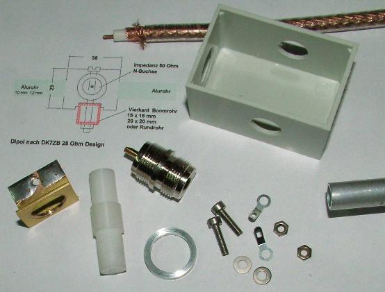
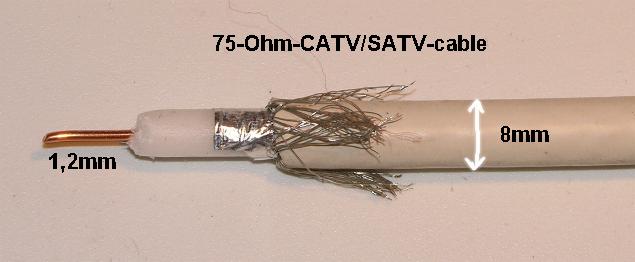
With 2xRG-59 (MIL-quality!) you can handle 300Wtts on 2m. The given or calculated lengths is related to the shield with short leads.
![]()
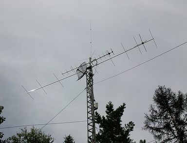
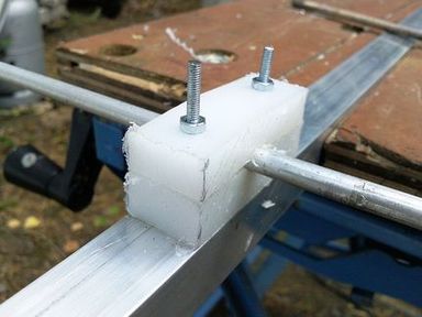
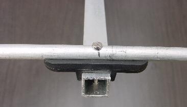
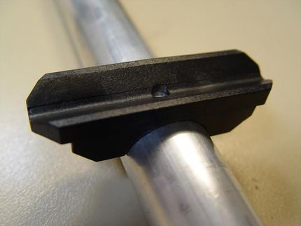
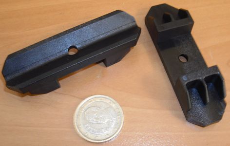
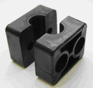
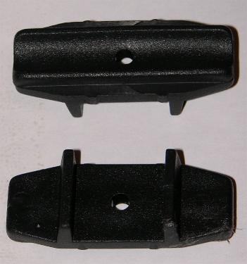
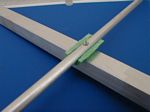
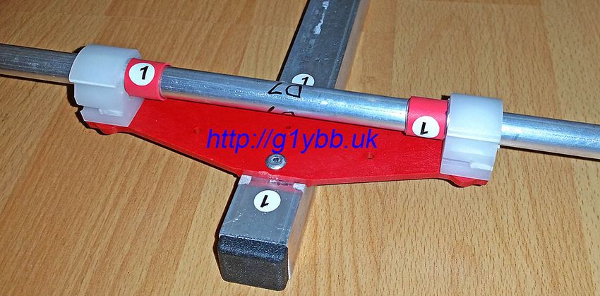
All DK7ZB-Longyagis have insulated mounted elements above the boom. That is the best way for mounting, because the formulas for mounting through the boom and on the boom are not very trustworthy. The factor for the longer elements in that cases must be another for the several directors. One constant factor is not a good choice.
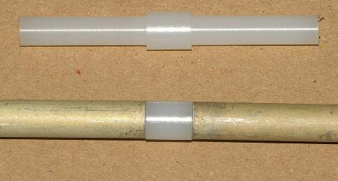
I prefer elements with 8mm or 10mm diameter, because they are much less critical than smaller diameters, e.g. 4mm. Bandwidth and tolerance against rain, fog and stacking harnesses are much better with thicker elements, keep that in mind!
|
|
The elements are mounted insulated with Polyamid- clamps (Konni), the screw in the electrical "zero-point" has no influence to the length of the element and is connected to the boom. "Insulated" means, that no part of the element is "short-cut", e.g. by the metal of the boom. |
![]()
Here an other interesting source for several holding clamps for round and square booms
by Pablo, EA4TX:
![]() |
|
Link to his page: http://interlanco.com/shop/index.php?main_page=index&cPath=36_37
![]()
|
Clamps for 20x20mm-Boom and 25x25mm-Boom distributed by Henryk, SP6GWN e-mail:sp6gwn@wp.pl
For 15x15mm and 20x20mm-clamps also try it at www.nuxcom.de |
|
|
Another method with homemade clamps (cheap and easy) by Adam, 9A4QV. See further details on his homepage: |
|
![]() |
Homemade holder by Sergey, RW3TU |
Short data for the Yagis:
| Type | Boomlength | Gain | F/B | G/T (4x) |
| 9-Element | 5,00m (2,4 WL) | 12,5dBd | >30dB | -3,41 |
| 10-Element | 6,00m (2,88 WL) | 13,1dBd | > 30dB | -2,8 |
| 12-Element | 8,00m (3,84 WL) | 14,2dBd | >30dB | -1,6 |
| 14-Element | 9,90m (4,73 WL) | 15,0dBd | > 30dB | -0,77 |
| 17-Element | 12,10m (5,83 WL) | 15,8dBd | > 40dB (!) | +0,12 |
Important:
If you use correction factors (DL6WU-formula) for non-insulated mounting through thicker booms with 30-40mm diameter, you must be sure, that the operating frequency has not changed.
You find that out by measuring the horizontal pattern. Look for the frequency, where the deep minimum between the main lobe and the first side lobe disappears. This frequency is about 1,5-1,7MHz above the design-frequency of my 28-Ohm-Longyagis. The picture shows this for the 12-Element-DK7ZB at 146MHz:
|
Pattern at 144.3 MHz |
Pattern at 146.0 MHz |
You can see two phenomena: The minimum at 330/30 degrees disappears (look for the pattern of the 12-Ele at 144.300MHz) and the F/B-ratio is 10-15dB worse in relation to the designing frequency. If you have found out the real operating frequency of your longyagi, you can correct the element-lengths if needed.
![]()
Construction of a long Boom with 20x20mm-square Aluminium

![]()
