Theory of the DK7ZB-Match (new) The "classic" DK7ZB-Match  Full symmetrical 28-Ohm-Match by DF9IC "Sperrtopf" by DF7DJ

The DK7ZB-Match for Yagis

It is a well known phenomenon, that the radiators resistance in a Yagi-structure drops down by adding parasitic elements to a dipole as a radiating element.

For the VHF-Bands (50-50.5MHz, 144-146MHz, 430-440MHz) a radiation resistance of 25-35Ohm has the best balance for gain, back- and sidelobes, bandwidth and SWR at tenable losses in a Yagi.

The classic match for that resistance/impedance is the Gamma-Match. The Beta-Match is a good choice as well, but realisation on VHF is difficult for homebrewing. For that reason a new simple, easy to built match was developed in 1995 for Yagis with resistitive loads of 12.5, 18 and 28 Ohm.

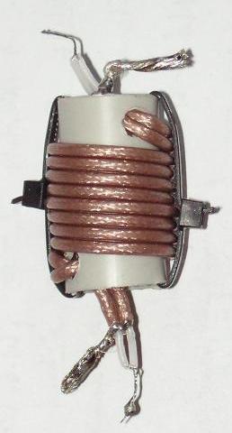
To understand how the "DK7ZB-Match" works look at the left picture. Inside the coax cable we have two currents I1 and I2 with the same amount but with a phase shift of 180°.

If we connect a dipole or the radiator of a Yagi direct to the coax, a part of I2 is not running to the arm 2 but down the outer part of the coax shield. Therefore I1 and I4 are not in balance and the dipole is fed asymmetric.

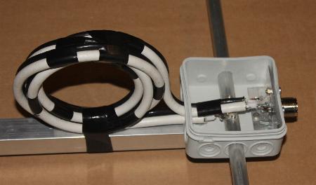
But how can we suppress the common-mode current I3? A simple solution is to ground the outer shield in a distance of lambda/4 at the peak of the current.

But now we get a new interesting problem: For the transformation 28/50 Ohm we need a quarterwave piece of coax with an impedance of 37,5 Ohm (2x75 Ohm parallel). The velocity of the wave inside the coax is lower than outside (VF = 0,667 for PE).

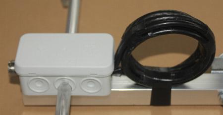
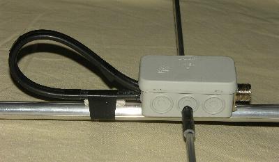
The outside of the shield has air (and a litle bit of insulation) in the surrounding and VF = 0,97. For grounding the common mode currents this piece should have a length of 50 cm, with a VF = 0,667 and a length of 34,5 
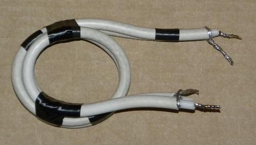
cm this piece of coax is to short. By making a loop of this two cables as shown in the picture down we get an additional inductivity and we come closer to an electrical length of lambda/4. Ideal is coax cable with foam-PE and a VF = 0,82. 

With a good grounding of the coax socket to the boom in practise no common mode currents are on the coax cable and the antenna has a symmetrical pattern!

Important hint:

The 2x75-Ohm-coax-cables (or 2x50-Ohm) for the match 28/50 Ohm (or 12,5/50 Ohm) must be absolutely parallel. If you mount them above the boom, take a piece of insulated material (uncritical) of 5 mm thickness between the cables and the boom.The high voltage at power >300W RF can cause a short circuit or arcing between screen and boom! This mounting avoids stray capacities against the boom, too.

The basic principle is a quarter-wave line of two coax-cables in parallel. One end of the line ist connected to the radiator, the other to a socket, which is grounded at the metallic boom and has two functions:

1. It transforms the  resistance of the radiator to the 50Ohm of the feeding line.  

With 2x75-Ohm-cables 28 to 50 Ohm. 

With 2x50-Ohm-cables 12.5 to 50 Ohm. 

With 3x93-Ohm-cables 18 to 50 Ohm

2. This line is a simplified coaxial sleeve balun to avoid sleeve-waves on the braid of the cable running to the station. Very effective!

Antennas which that match have some advantages:

   -  You do not need a folded dipole or any exotic radiators like loops, the length of a normal dipole can be     corrected easier.

   -  The radiation pattern is very clear.

   -  Simple mechanical solution for the match with the coax-cables.

   - For shortwave and 6m you can wind the cable to a choke with an additional suppression of sleeve-waves

With usual  coax of  50 and 75  Ohm the following cases are interesting:

Radiation resistance Z of the Yagi

Lambda/4 Coax-cable

 Impedance of the line

12.5 Ohm

2x50 Ohm parallel 25 Ohm
18 Ohm 50+75 Ohm parallel 30 Ohm
28 Ohm 2x75 Ohm parallel 37.5 Ohm

12.5-Ohm: Good for high-gain  yagis with small bandwidth in the 6-m- and 2-m-Band, losses tenable

18-Ohm: Can be used on 6m and 2m, medium bandwidth

28-Ohm: Best balance for all antenna parameters on 2 m and 70 cm

Update: The 18-Ohm-Match in practise

It is possible to use 50- and 75-Ohm-cable in parallel. The condition is the same VF. That means we can use cable with Full-PE (VF=0,67) or Foam-PE (VF about 0,82) with the same lengths. I have tested this method in various antennas with excellent results.

For example two impedance matches for 50-MHz- and 70-MHz-Yagis:


Here two cables RG58 (50 Ohm) and RG6 (75 Ohm) in parallel. The two cables have different diameters,  but the same VF of 0,67. The 70-MHz-Yagi has a perfect match from 18 to 50 Ohm.

This is a 50-MHz-Yagi with cables of VF=0,82. 50 Ohm with Aircell-5 (5 mm diameter) and a CATV-cable 75 Ohm with 6,5 mm diameter. Perfect match from 18 to 50 Ohm in a 50-MHz-Yagi.

The 2-m-28-Ohm-DK7ZB-match in practise

The best suppression of the common wave currents can be get with a cable of V=0,82. Here I have used a 7-mm-SATV-cable with 75 Ohm.

The length is 42,5 cm (refered to the braid!).

The additional inductivity of the turn leads to a self resonance near 144 MHz and a very good balance of the feeding.


The 28-Ohm-match with 2x75-Ohm-CATV/SATV-cable shown above will handle 750 Wtts RF on SSB/CW on 2 m and >1KW on 50 MHz. Do not bend the loop with a to small diameter! The V (Velocity of propagation) with these cables is in the range of 0,8-0,85, most cables have a V=0,82. Use a good quality, in the last time a lot of inferior cables with a steel braid are on the market.

With 2xRG59 (good MIL-quality!) you can handle 500 Wtts on 2 m and 1 KW on 50 MHz. The given or calculated lengths is related to the shield. Keep the leads as short as possible.

Another type of an impedance choke for 2m:

2x RG179 PTFE-cable parallel  wound to a choke. The length is 2x 37 cm (braid).

This choke can be loaded with 500 Wtts SSB/CW power

There is a lot of 75-Ohm-CATV-cable with good electrical data. The only problem is the screen, which is often made in Aluminium and cannot be soldered.

Here is the solution of Jörg, DG1JC:

Use an end sleeve for strands and you have a simple and effective method.

There are people criticysing the medium (28 Ω) an low (12,5 Ω) impedance Yagis and have speculations about any mystic losses in the match for that feedpoint impedances. But the same people use stacking harnesses and splitters exact with such impedance points of 25 Ω and 12,5 Ω at the connections for matching. Nobody believes that this has any disadvantage.

Paul, GW8IZR, has made an independent measuring of the losses in such a match 12,5  Ω to 50 Ω with the following test circuit:

With two of such transformation sections back to back he measured the losses against a halfwave piece of straight coax. His results for 2x RG58 (a more lossy cable you will not find...) and 40 MHz:

Upper graph: A piece of 50-Ω-coax with the length of lambda/2

Lower graph: Two matching sections parallel back to back

The difference is -0,025 dB. Do you think we should talk about that? If you use better cables the difference will be less. If you construct a 50-Ω-choke for feeding a 50-Ω-Yagi or a choke with 2x75-Ω- or 2x50-Ω-cables in parallel makes no difference in the losses!

A lot of antennas were built for the 6-m-, 2-m- and 70-cm-Band. The performance of the Yagis is excellent. Meanwhile stations in many countries are using Yagis with the DK7ZB-match.


Left:

The vertical 3-Element-Yagi is built by Peter, PA4PS for use on a 202,5-MHz-link to the FM-Radiostation Havenstad FM in the Netherlands.

The Yagi is a 28-Ohm-type with the DK7ZB-match.

Seems to be the first time that a DK7ZB-Yagi is used by a commercial station....

1. Long-Yagis for the 2m-Band with 28-Ohm-technology got the first price in the technical competition of the German Ham-Magazine "FUNKAMATEUR" 1996.

2. See the VE7BQH-List for 2m-Yagis, the DK7ZB-Yagis have good gain and pattern.

3. The DK7ZB-Match got the first price (part "ANTENNAS") in the construction-competition at the German  VHF-Convention in Weinheim 2000.

4. Meanwhile  a lot of Yagis with the DK7ZB-Design  are used in several countries, reports about the yagis can be found in many HAM-Magazines and the internet. Many VHF-/UHF-contest-crews are working with stacked arrays of these Yagis.

The DK7ZB-Match is working  quite well in practice: DO1IR built up the 6-Element-144MHz-Yagi and corrected only the length of the radiator-element.

With an HP-Networkanalyzer HP 8713-C he tested the antenna. Look for the result: The reflected wave is damped >50dB! Compare that with other commercial built Yagis.....