|
E12 series
10% tolerance |
E24 series
5% tolerance |
| 10 |
10 |
| 11 |
| 12 |
12 |
| 13 |
| 15 |
15 |
| 16 |
| 18 |
18 |
| 20 |
| 22 |
22 |
| 24 |
| 27 |
27 |
| 30 |
| 33 |
33 |
| 36 |
| 39 |
39 |
| 43 |
| 47 |
47 |
| 51 |
| 56 |
56 |
| 62 |
| 68 |
68 |
| 75 |
| 82 |
82 |
| 91 |
Resistors are made in multiples of these values, for example, 1.2  , 12 , 12  , 120 , 120  , 1.2 , 1.2  , 12 , 12  , 120 , 120  and so on. and so on.
Consider 100  and 120 and 120  , adjacent values in the E12 range. 10% of 100 , adjacent values in the E12 range. 10% of 100
 is 10 is 10  , while 10% of 120 , while 10% of 120  is 12
is 12  . A resistor marked as 100 . A resistor marked as 100  could have any value from 90 could have any value from 90  to 110 to 110  , while a resistor marked as 120 , while a resistor marked as 120  might have an actual resistance from 108 might have an actual resistance from 108  to 132 to 132  . The ranges of
possible values overlap, but only slightly. . The ranges of
possible values overlap, but only slightly.
Further up the E12 range, a resistor marked as 680  might have and actual resistance of up to 680+68=748 might have and actual resistance of up to 680+68=748  , while a resistor marked as 820 , while a resistor marked as 820  might have a resistance as low as 820-82=738 might have a resistance as low as 820-82=738  . Again, the ranges of possible values just
overlap. . Again, the ranges of possible values just
overlap.
The E12 and E24 ranges are designed to cover the entire resistance range with the
minimum overlap between values. This means that, when you replace one resistor with
another marked as a higher value, its actual resistance is almost certain to be
larger.
From a practical point of view, all that matters is for you to know
that carbon film resistors are available in multiples of the E12 and E24 values. Very
often, having calculated the resistance value you want for a particular application, you
will need to choose the nearest value from the E12 or E24 range.
Current limiting
You are now ready to calculate a value for the resistor used in series with an LED.
Look at the circuit diagram:

A typical LED requires a current of 10 mA and has a voltage of 2 V across it
when it is working. The power supply for the circuit is 9 V. What is the voltage
across resistor R1? The answer is 9-2=7 V. (The voltages across components in series
must add up to the power supply voltage.)
You now have two bits of information about R1: the current flowing is 10 mA, and
the voltage across R1 is 7 V. To calculate the resistance value, use the formula:
 |
Substitute values for V and I:

Look out! The formula works with the fundamental units of resistance, voltage and
current, that is, ohms, volts and amps. In this case, 10 mA had to be converted into
amps, 0.01 A, before substitution.
If a value for current in mA is substituted, the resistance value is given in  : :

The calculated value for R1 is 700  . What are the nearest E12/E24 values? Resistors of 680 . What are the nearest E12/E24 values? Resistors of 680  , 750 , 750  and 820 and 820  are available. 680 are available. 680  is the obvious choice. This would allow a
current slightly greater than 10 mA to flow. Most LEDs are undamaged by currents of
up to 20 mA, so this is fine. What is the colour code for a 680 is the obvious choice. This would allow a
current slightly greater than 10 mA to flow. Most LEDs are undamaged by currents of
up to 20 mA, so this is fine. What is the colour code for a 680  resistor? resistor?
Resistors in series and parallel
In a series circuit, the current flowing is the same at all points.
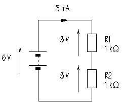
The circuit diagram shows two resistors connected in series with a 6 V battery:
 Resistors in series Resistors in series
It doesn't matter where in the circuit the current is measured, the result will be the
same. The total resistance is given by:
 |
In this circuit, Rtotal=1+1=2  . What will be the current flowing? The formula is: . What will be the current flowing? The formula is:
 |
Substituting:

Notice that the current value is in mA when the resistor value is substituted in  . .
The same current, 3 mA, flows through each of the two resistors. What is the
voltage across R1? The formula is:
 |
Substituting:

What will be the voltage across R2? This will also be 3 V. It is important to
point out that the sum of the voltages across the two resistors is equal to the power
supply voltage.
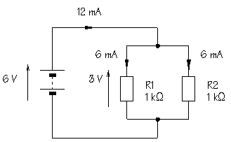
The next circuit shows two resistors connected in parallel to a
6 V battery:
 Resistors in parallel Resistors in parallel
Parallel circuits always provide alternative pathways for current flow. The total
resistance is calculated from:
 |
This is called the product over sum formula and works for any two
resistors in parallel. An alternative formula is:
 |
This formula can be extended to work for more than two resistors in parallel, but lends
itself less easily to mental arithmetic. Both formulae are correct.
The current can be calculated from:

How does this current compare with the current for the series circuit? It's more. This
is sensible. Connecting resistors in parallel provides alternative pathways and makes it
easier for current to flow. How much current flows through each resistor? Because they
have equal values, the current divides, with 6 mA flowing through R1, and 6 mA
through R2.
To complete the picture, the voltage across R1 can be calculated as:

This is the same as the power supply voltage. The top end of R1 is connected to the
positive terminal of the battery, while the bottom end of R1 is connected to the negative
terminal of the battery. With no other components in the way, it follows that the voltage
across R1 must be 6 V. What is the voltage across R2? By the same reasoning,
this is also 6 V.
| KEY POINT: |
When components are connected in parallel, the voltage across them is the same. |
Resistors - Final Page >>>
|


 Resistors in series

 Resistors in parallel


