PLL UHF with LMX2324 & PIC16F628
![]() Here Old Project LMX2324/U37SL (link)
Here Old Project LMX2324/U37SL (link)
About LMX PLL
I build this PLL for UHF transverters (432MHz,1296MHz). The new design use simulation with ADIsimPLL Software. PLL active loop filter improve the spurious rejection.
For best performance the reference frequency must be high . In my case i use 400KHz because de N divider must be limited to 992. LMX2324 N divider support between 992 and 32767 (see datasheet).
Example:
Fq=404MHz, Phase Detector Reference=400KHz =>N Divider=1010
Fq=1152MHz, Phase Detector Reference=400KHz =>N Divider=2880
I recommend a VCO with low KV factor (MHz/V), phase noise will be improved.
-VCO Frequency: 404MHz
-Reference Oscillator: 16,8MHz VTCXO
-Phase Detector Frequency: 400KHz
-Loop Filter: Active Low Pass with AD8510 (Simulation Model CPA_PPFFBP1) -Use a good Operational Amplifier!
-Loop Bandwith: 4KHz (better for spurious rejection)
-VCO KV factor: 0,5MHz/V
-CP Polarity: Negative (is inverted by Operational Amplifier)
For simulation i use ADF4112, Phase Detector Resistor=4,40K, Current Charge Pump=4mA (LMX2324 have CP=4mA)
LMX2324 specifications
Input Level: -15dBm...0dBm (works with less than -15dBm)
Input Main Frequency: max. 2GHz (I tested U37SL Fujitsu IC PLL up to 2,2GHz, U37SL is compatible with LMX2324)
Input Reference Frequency: max. 40MHz / Level min. 0,3-0,4Vpp
Power Supply: Vcc=2,7V...5,5V; Vpp=Vcc...5,5V
Software
The PLL is controlled by Microwire Interface. I chose PIC16F628A to generate the three line "word". The software is easy to use:
— Source code must be modified accordingly. In the source code we need to insert the "word" for the preferred parameters.
— Code Loader 4 is used to calculate the mysterious "word". Select LMX device, insert VCO frequency, Reference, CP polarity, then copy/paste the resulting binary values.
— After that source code is compiled by MPLAB + Hi-Tech C and hex file is obtained.
Thanks Vasea for free firmware! This code is easy to modified for LMX PLL Series. Software dedicated ONLY for HAM-Radio purpose.
![]()
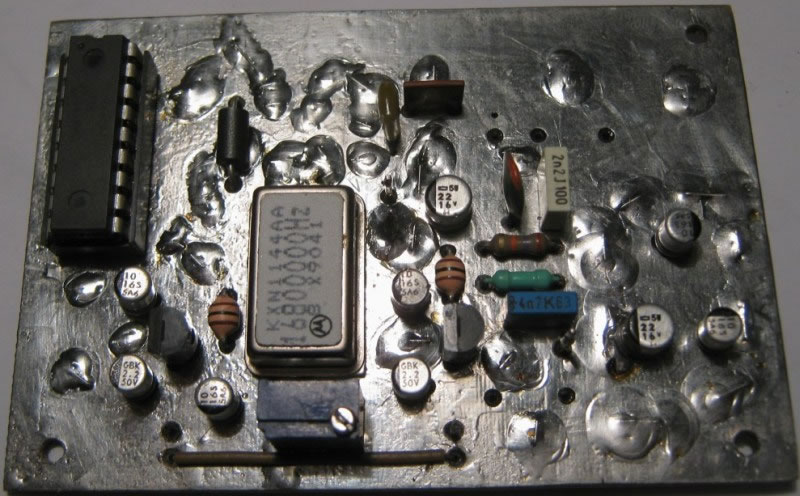
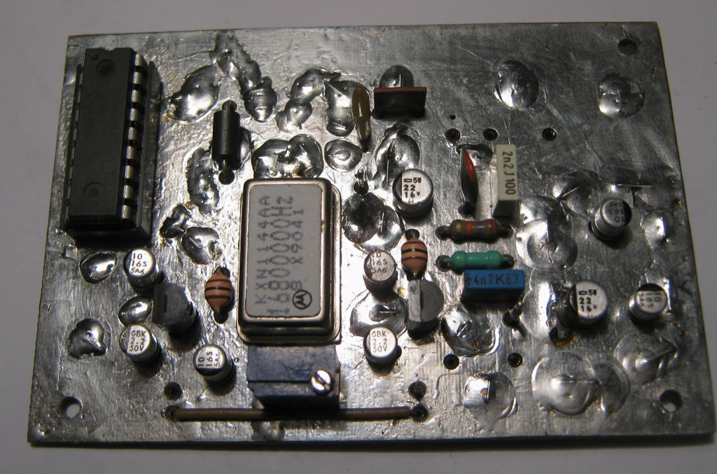
![]() PCB Photo (my PCB is slightly different - ICL7660 +9/-9V is not used)
PCB Photo (my PCB is slightly different - ICL7660 +9/-9V is not used)
![]() Schematic diagram
Schematic diagram
![]() PCB Layout vers.2: Bottom (1:1) & Position components
PCB Layout vers.2: Bottom (1:1) & Position components
![]() Source Code for PIC16F628 - Binary Word (vers. 2013) & Hex Word (vers. 2011)
Source Code for PIC16F628 - Binary Word (vers. 2013) & Hex Word (vers. 2011)
![]() Hex File (404MHz, OSC=16,8MHz, CP=Negative, REF=400KHz)
Hex File (404MHz, OSC=16,8MHz, CP=Negative, REF=400KHz)
![]() Tutorial - How to edit Source Code (Binary Word version)
Tutorial - How to edit Source Code (Binary Word version)
![]() ADIsimPLL 3.41
ADIsimPLL 3.41
![]() Code Loader 4
Code Loader 4
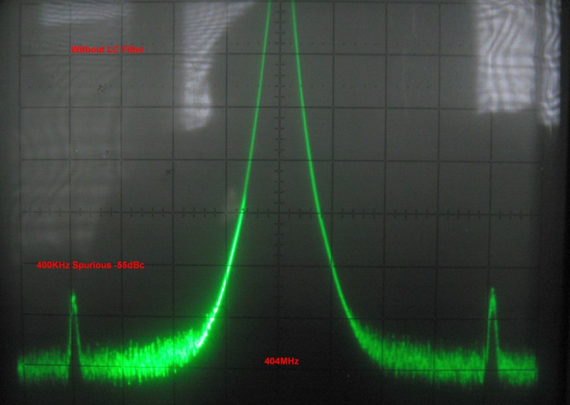
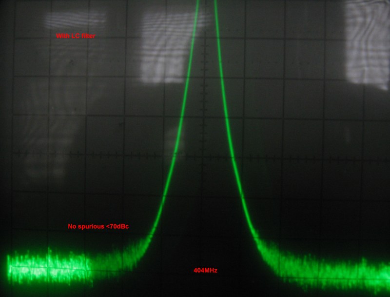
Spectrum Analyser Photos (SPAN=100KHz/div, BW=10KHz, Video Filter=OFF). Rejection of 400KHz spurious:
![]() Without Optional LC Low Pass Filter
Without Optional LC Low Pass Filter
![]() With Optional LC Low Pass Filter
With Optional LC Low Pass Filter
yo4hfu@2010-2026