HP8648 Signal Generator Repair |

HP8648 is an entry level signal generator with a good price on Ebay. My first HP8648C (9KHz-3,2GHz) bought in good condition was a pleasure, easy to operate, good accuray and enough frequency range. It can be remote controled via GPIB (HP-IB) bus. After this experience i found one more HP8648B (9KHz-2GHz), very cheap, but "no output" according seller description. I didn't notice other error in the seller's photos, maybe only the stepped attenuator has an issue. In reality was a "small" disaster. Below is a summary of my experience during HP8648B repairing.
#1. Output stepped attenuator out of order, as expected. Output level has abnormal attenuation steps.
#2. Error 627 during power up due to missing battery
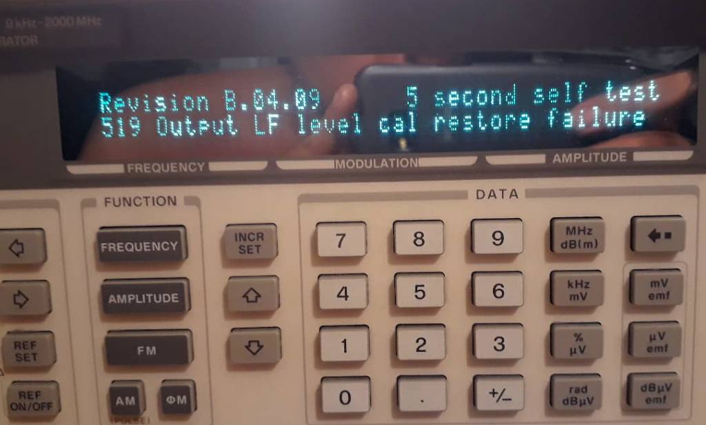
#3. Error "519 Output LF level cal restore failure"
#4. Output level can't be adjusted by vernier if the frequency is less than 1GHz.
#5. Error "608 Synth out-of-lock: Main"
#6. Error "605 ALCout-of-lock: Div, HET, Main, X"
#7. Error "518 Atten comp loss cal restore failure" (20.11.2018)
As you can know for HP8648A/B/C/D and HP8647, service manual has not included schematic diagrams and general content is poor in case you need to repair something. HP advice is to replace faulty module, very simple... Also it is almost impossible to calibrate without dedicated instruments. HP8648 is designed for automated calibration via HP-IB bus. Indeed, very bad news for us but not impossible. We will see how to fix above malfunction, without to be expensive.
Some modules used by Agilent 8648 are similar with Agilent 8920, but not exactly the same. Also Agilent 8920A Service Manual is better than 8648.
For example here are diagrams for Reference Unit, Signal Generator Synth and Output RF extracted from 8920 manual. See also the 8920 schematics!
![]()
![]() HP8648 Operating and Service Guide
HP8648 Operating and Service Guide
![]() Agilent 8920A Service Manual - schematics included!
Agilent 8920A Service Manual - schematics included!
![]() Agilent 8920A manual - block diagrams
Agilent 8920A manual - block diagrams
![]() 10MHz Timebase adjust. Good quality VHF frequency counter required.
10MHz Timebase adjust. Good quality VHF frequency counter required.
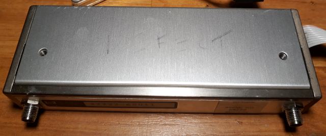
#1. Output attenuator marked as "Defect". Part No. 33322-60011
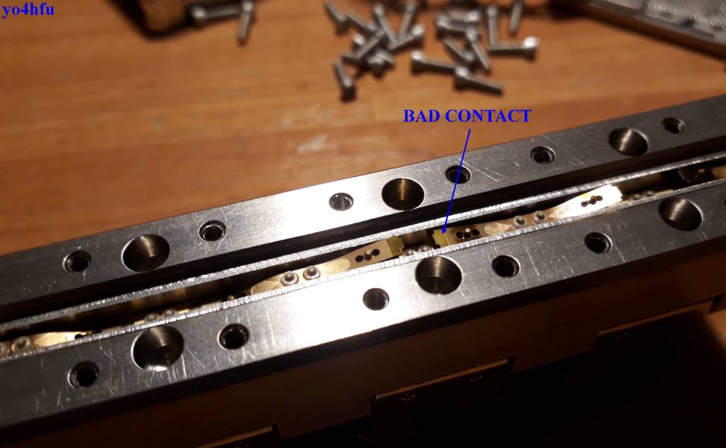
Resistive pads (10/20/40/60dB) were found in good order, no burned or cracked resistors. Abnormal behaviour observed when 20dB step is engaged. As you can expect i found bad rubber O-rings and solenoid coil didn't switched one contact. Path of signal disturbed by this wrong open contact.
Solution: open attenuator assembly and replace all small Orings (OD 2mm / ID 1mm/ CS 0.5mm).
O-rings source: AliExpress seller (01.09.2018, dead link), 2x1x0.5mm NBR, 50pieces, ~10$
Internal view of attenuator:
![]()
![]() Defect Stepped Attenuator
Defect Stepped Attenuator
![]() Bad contact - not fully engaged
Bad contact - not fully engaged
![]() How to take out magnets and driver board
How to take out magnets and driver board
![]() Missing O-rings, commun problem of HP stepped attenuators
Missing O-rings, commun problem of HP stepped attenuators
![]() Better view of rubber orings, all pieces are in poor condition
Better view of rubber orings, all pieces are in poor condition
#2. Error 627 during power up due to missing RAM memory battery
Battery is not in place, somebody try to replace it. Also i found free and losen bolts inside of generator box. We will see below what happen if you power up motherboard and few bolts are free to move under PCB.
During power up the software try to reload calibration parameters from every module Motherboard/Reference/Synthesizer/Output/Extension. Every module has unique "ROM". Battery is used to keep SRAM memory alive, user settings and configuration of installed modules. Without battery RAM memory will be reloaded during start-up using default "ROM" instructions.
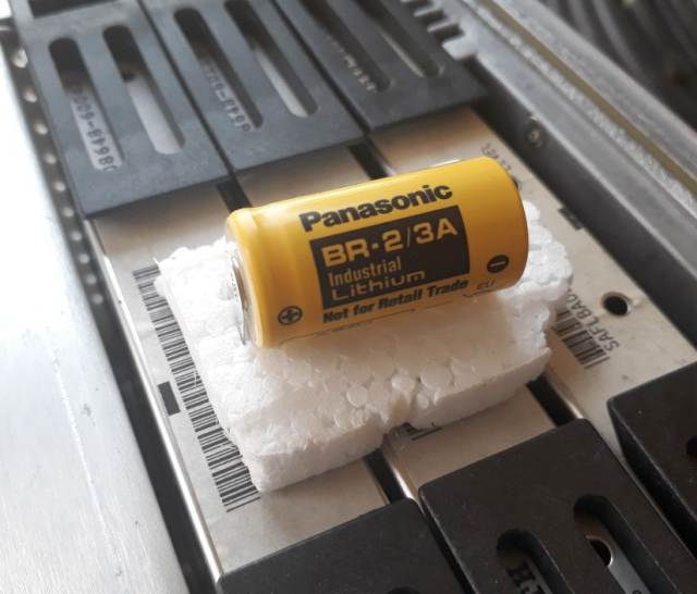
BR-2/3A 3V Lithium. Do not try to recharge! Replace battery and will be fine.
#3. Error "519 Output LF level cal restore failure"
This error is a real problem, it is not even mentioned in the manual! Searching over Internet i found only one answer: "A6 Output Module has calibration problems or motherboard need to be replaced"... I can't run any calibration via HP-IB bus and to replace motherboard is to much for me. My HP8648B will be available for spare parts?! :). I didn't notice any anomaly of generator if 519 error is active, i'm not sure 100% because i didn't check 9KHz-100KHz output level.
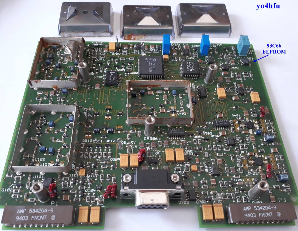
Don't worry, i have one more generator HP8648C, so let's start to experiment. One by one i start to replaced module between generators in order to locate 519 Error. If I replace "A6 Output Assembly", the error disappears! Very good, i know were to dig deep. What is inside of A6 Output Module, how calibration are stored? ROM memory is used (according service manual) to store calibration parameters. In reality ROM memory is a EEPROM microwire memory 93C66 or 93C46 . Hmm i have some ideas to copy calibration file from good A6. I need to mention, if you take out EEPROM and you try to start A6 module, same 519 will be received.
![]()
![]() A6 Output Module. Rusted screen shields but PCB in good condition and requires a good cleaning. 93C66 location visible.
A6 Output Module. Rusted screen shields but PCB in good condition and requires a good cleaning. 93C66 location visible.
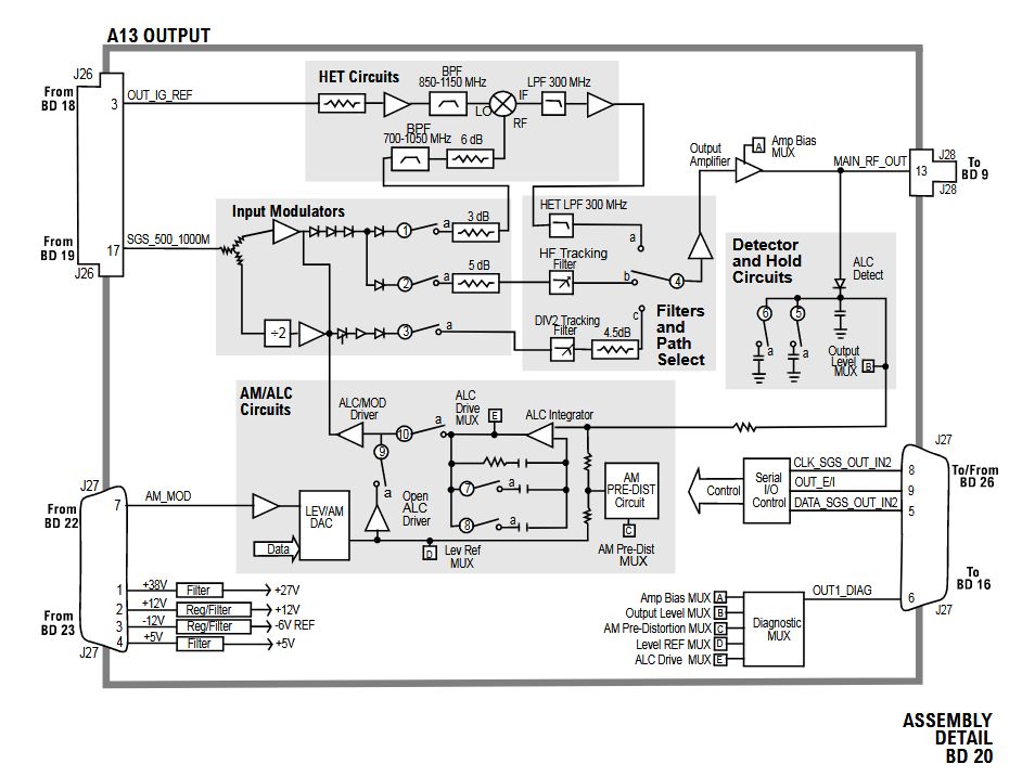
![]() HP8920 Output Module, similar with A6/HP8648, schematic diagram (missing ALC INT/EXT switch DG413, anyway A6 INT ALC is not used for B/C/D, only for A version)
HP8920 Output Module, similar with A6/HP8648, schematic diagram (missing ALC INT/EXT switch DG413, anyway A6 INT ALC is not used for B/C/D, only for A version)
For 93Cx6 programming I use an old laptop with native serial port (no USB/RS232 adapter), Windows XP and PonyProg 2000 software. Choose 16 bit mode of 93Cxx leave pin no.6 OPEN (floating) or to VDD, do not connect to GND (8bit mode).
Any EEPROM 93Cxx programmer can be used.
![]()
![]() Schematic of 93Cxx programming interface
Schematic of 93Cxx programming interface
![]() PCB Sprint-Layout 6 file
PCB Sprint-Layout 6 file
![]() PonyProg 16 bit selection
PonyProg 16 bit selection
After EEPROM programming, 519 error is clear, well done! OK is not perfect solution to use calibration file from other module. Testing between 9KHz-100KHz reveals poor calibration of output level under 25KHz. Corrupted A6 Module type 08648-60116.
-NEW UPDATE (11.09.2018) I have one more HP8648C (LCD version) in good condition. LF response of defective HP8648B is more better using that calibration file.
![]()
![]() A6 Output Assembly 08648-60192 (without variable resistors), EEPROM 93C66 "bin" dump
A6 Output Assembly 08648-60192 (without variable resistors), EEPROM 93C66 "bin" dump
![]() NEW A6 Output Assembly 0648-60131 (with variable resistors), EEPROM dump
NEW A6 Output Assembly 0648-60131 (with variable resistors), EEPROM dump
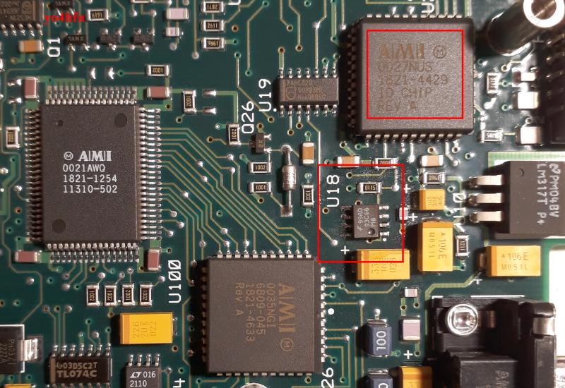
Inside of HP8648 you can locate 6 pieces 93Cxx EEPROMs, connected to SCX6206TQM IO Chip. I found one more version of A5 module using AMI IO Chip. Because is a big trouble to loose one of memory parameter, i made full backup of all 12 pieces EEPROM, from both generators HP8648B and HP8648C. Original corrupted file of A6 HP8648B is not available. Below you can download my BIN files in case you have trouble. Please take care and don't blame me if something bad happens! Before any EEPROM programming, make a backup of original file, even if is corupted or unknown condition! Also i recommend to test programming interface using spare 93CX6.
You can mix all modules between HP8648 B/C, only A10 Frequency Extension will not work above 1GHz. Also if you take out A10, RF signal is still active on SMC connector (from A6 output).
![]()
LE: 23.08.2025 - programming by XGECU TL866+ required selection of "8bit" and "SWAP". Different way to dump EEPROM betewwn PonyProg and XGECU?
Anyway, try different settings 8/16, SWAP, util the EEPROM is correct recognized by 8648.
| EEPROM CALIBRATION BIN DUMPS FROM HP8648B/C (VFD version) | |||
|---|---|---|---|
| HP8648B SN: 3426A00391 |
Observation | HP8648C SN: 3847U3029 |
Observation |
| Motherboard U59 | Located under Attenuator MB revision B.04.09 |
Motherboard U59 | Located under Attenuator MB revision B.04.09 |
| Motherboard U201 | Located under Fan MB revision B.04.09 |
Motherboard U201 | Located under Fan MB revision B.04.09 |
| A4 REFERENCE | Option 1E5 08648-60042 93C46 |
A4 REFERENCE | STANDARD 08647-61045 93C46 |
| A5 SIG GEN SYNTH | 08648-60115 SCX6206TQM IO Chip |
A5 SIG GEN SYNTH | 08648-60115 AMI IO Version |
| A6 OUTPUT | Not Available/Corrupted 08648-60116 (with variable resistors) |
A6 OUTPUT | 08648-60192 (without variable resistors) |
| A10 FREQ. EXTENSION | 08647-60213 | A10 FREQ. EXTENSION | 08648-63191 |
|
EEPROM CALIBRATION BIN DUMPS - NEW HP8648C (LCD version) Not full backup for the moment (11.09.2018) |
|
|---|---|
| HP8648C SN: 3462U01161 |
Observation |
| Motherboard U59 | Located under Attenuator MB revision B.04.01 |
| Motherboard U201 | Located under Fan MB revision B.04.01 |
| A4 REFERENCE | 08647-61045 |
| A5 SIG GEN SYNTH | 08648-60115 |
| A6 OUTPUT | 08648-60131 (with variable resistors) |
| A10 FREQ. EXTENSION | 08648-60024 |