STEREO CODER 32X |
I hope to be useful for the amateur interested to build/experiment a good stereo coder and to learn about oversampling "modulators".
This web page contains information only for educational purpose!
Some features:
Professional Stereo Coder
Pilot 19KHz generated by 32x oversampling
DSB 38KHz 16x oversampling
Output S&H Filter at 608KHz
LC filter 150KHz/-3dB with good phase linearity
Excellent phase stability between 19KHz <-> 38KHz
Low Noise and good dynamic range
MPX output amplifier with BJT medium power
Power supply: +/-7.5V 0.1A
Simple adjustment procedure
Cheap components (CMOS 4000 and TL082/LF353 O.A.)
Description:
19KHz pilot carrier is obtained by 32x digital oversampling. Sinus waveform is digital synthesized using resistors ladder and 4051 CMOS switches. BCD decoder 4028 and Presettable Up/Down Counter 4029 provide switching algorithm for 4051. Second harmonic (38KHz) can be optimum rejected by 10K variable resistor (symmetry of sine wave).
The PCB was simplified how much was possible. Few "4081 OR gates" are replaced with 4148 diodes. PCB ground plane is present everywhere for good stability and low noise.
Same topology is used for 38KHz DSB generator, but 16x oversampling. Buffer stages are recommended between audio L/R channels and stereo coder inputs. 4051 generator is properly balanced when the inputs are connected to low impedance audio source. L&R input level is 6Vpp for 100% modulation. Pre-emphasis and 15KHz low pass filters must to be used in front of the stereo coder. Check Download section for some suggestions.
Both generators are filtered by Sample & Hold method. Digital noise generated during switching resistor taps, can be eliminated. In the next image both DSB and Pilot signals are filtered at 608KHz.
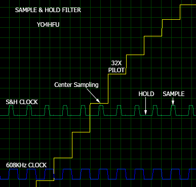
Switches 4066 (S1;S2) are turned ON for one-half of one clock cycle at the center of each stepped pilot waveform sample. This charge 330pF capacitor to the sample voltage value, which is held by operational buffer until next center sample is taken. Center sampling eliminates integration of switching noise that is concurrent with leading/trailing edges of the waveform steps.
After S&H filter, pilot carrier can be adjusted around of 10% of MPX level. DSB diode clipper circuit, helps for over modulation. Hard clipping is not recommended! MPX signal contain 38KHz and 19KHz mixed.
MPX signal is again LC filtered in order to eliminate 608KHz switching components. LC filter cuts at 150KHz/-3dB/300 ohms impedance. MPX phase isn't affected by this filter, this is a secret for good stereo separation.
Global phase stability is "rock" steady due synchronization mechanism between generators. Fine adjustment of phase/gain is possible around of MPX output amplifier in order to correct any nonlinearity.
The output stage ensure properly drive of any TX exciter. Push-pull bipolar amplifier can drive a 75 ohms load (long coaxial cable) without distortions.
Entire stereo coder needs 1,216MHz external clock. Quartz oscillator or other signal source can be used. My choice was SI5351 PLL IC controlled by ATMEGA328, cheap and flexible option. Update Jan 2025: SI5351 & Attiny clock generator
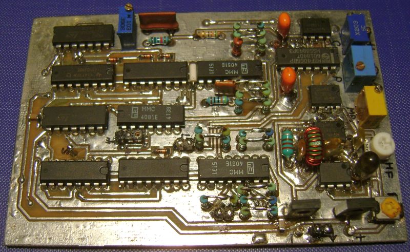
PCB prototype:
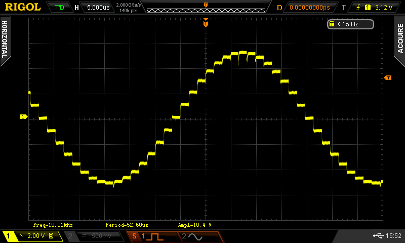
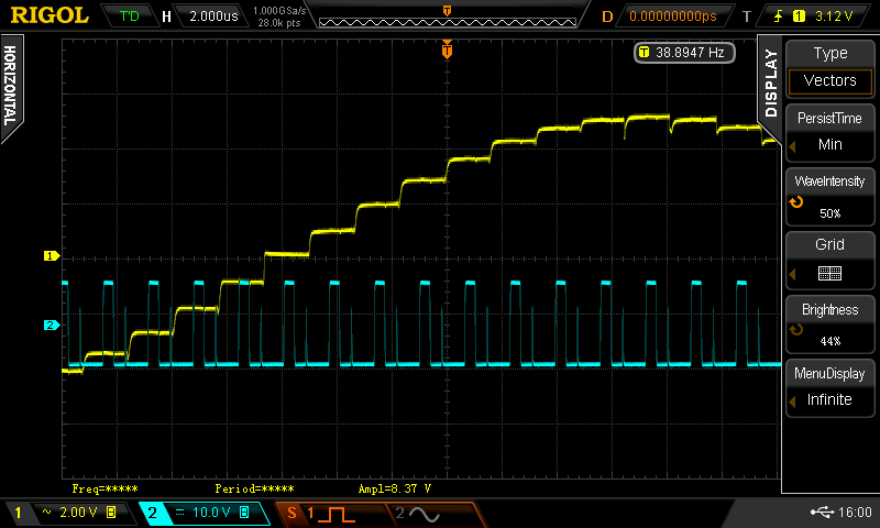
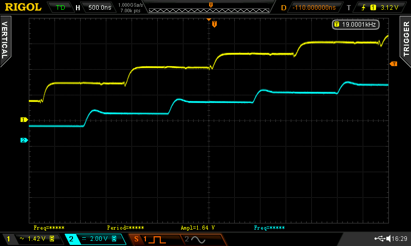
19KHz steps, 4051 output:
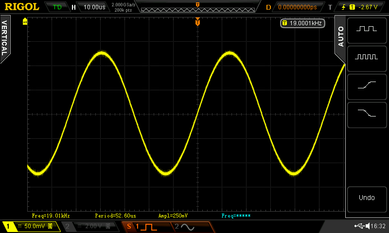
19KHz Pilot - MPX Output (0,25Vpp):
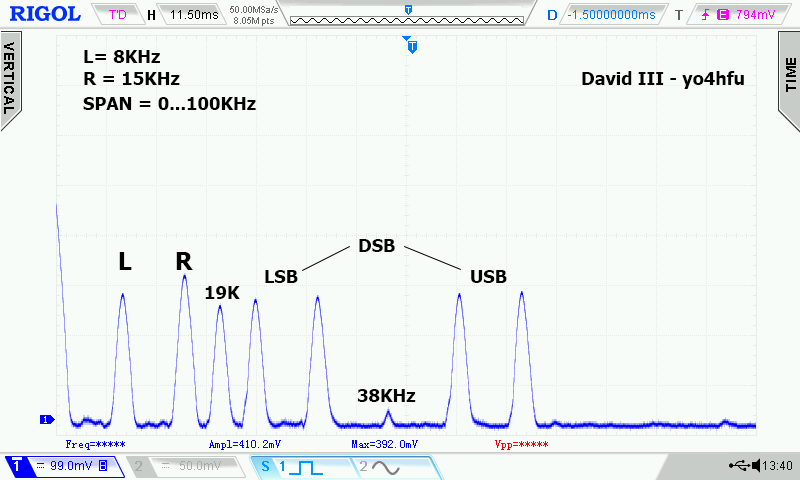
Spectrum analyzer connected to MPX OUT. Left and Right Channels were feed with 0,25V sine waves (to avoid overload SA frontend). Pilot 38KHz harmonic was intentionally adjusted for poor suppresion. In normal conditions, 19KHz 2nd harmonic is excellent rejected by "10K Harmonic Null" resistor. Below, Mono Left signal don't has same amplitude as Mono Right due poor response of spectrum analyzer at very low frequency. Measurements were done using HP8553B/HP8552B/DS2072, designed for 0,1-1250MHz. No spurious response or harmonics were detected above 100KHz.
![]()
![]() Schematic rev 1.1
Schematic rev 1.1
![]() PCB rev. 1.3 (tested OK) - Sprint Layout 6 file
PCB rev. 1.3 (tested OK) - Sprint Layout 6 file
![]() Pilot Generator 32x - switching sequence
Pilot Generator 32x - switching sequence
![]() Optional Voltage Reference for DSB Diode Clipper
Optional Voltage Reference for DSB Diode Clipper
![]() Optional RDS/Subcarrier auxiliary input
Optional RDS/Subcarrier auxiliary input
![]() Preemphasis and 15KHz LPF - Katruud
Preemphasis and 15KHz LPF - Katruud
![]() 7-pole FDNR LPF 16KHz (pre-emphasis required)
7-pole FDNR LPF 16KHz (pre-emphasis required)
Oscillograms:
Sample and Hold signal - wrong, double pulse
Sample and Hold signal fixed after 10K resistor connected to pin 13, AND gate IC19
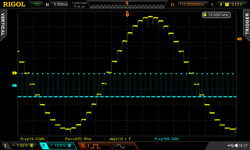
19KHz signal before (yellow) and after (blue) sample and hold filter