PLL SI5351A - ARDUINO ATMEGA328 |
The Si5351 is an I2C configurable clock generator that is ideally suited for replacing crystals, crystal oscillators, VCXOs, phase-locked loops (PLLs), and fanout buffers in cost-sensitive applications. Based on a PLL/VCXO + high resolution MultiSynth fractional divider architecture, the Si5351A can generate any frequency up to 160 MHz on each of its 3 outputs with 0 ppm error.
Price: aprox. 1$.
I choose to controll Si5351 by Atmega328 without external crystal oscillator. Many Si5351 Arduino applications can be found over Internet. A bootloader firmware was used for Arduino IDE compatibility. Arduino "sketch" is easy to be modified, any frequency can be set for Clock Output 0 or 1. Output 2 is not used by me, pin 6 is not connected on PCB. Three frequencies can be generated in same time with 0,1Hz resolution...fantastic chip. For details, see Si5351 datasheet.
Si5351A use a SMD external crystal 25MHz or 27MHz. Resonators with low parasitic capacitance give best results. I used with good results standard crystals recovered from PC Video Cards (do not use a crystal resonator with +Vcc pin, otherwise PCB must to be modified). TCXO Abracon ASTX-H11-25.000MHZ-T is preferably for special applications, need 3,3V power supply.
Atmega 328 Software Configuration
1. Bootloader Upload
First solder Atmega328 TQFP package and LD1117-3.3 voltage regulator. Also Si5351A can be connected during bootloader upload.
We need a Arduino Board UNO or other version to send the bootloader inside of new Atmega328. Connect Arduino UNO to PC using a USB cable. Do not forget about Arduino IDE software, any version can be used.
Unzip Arduino_Sketches_master (http://www.gammon.com.au/breadboard). Open Atmega_Board_Programmer folder and Atmega_Board_programmer arduino file .
Make next settings: Tools/Board/Arduino Uno and Tools/Serial Port/Com X (emulated serial port, check Hardware Manager in order to find Arduino COM number).
Upload the Sketch.
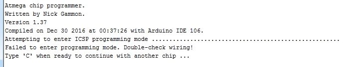
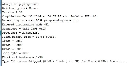
Open Tools/Serial Monitor at 115200 baud. If Arduino UNO was programmed properly, this message can be see:
Now connect Si5351A/Atmega328 to Arduino UNO Board (disconnect USB for safety). ArduinoUNO connected to Si5351A board. Click to zoom:
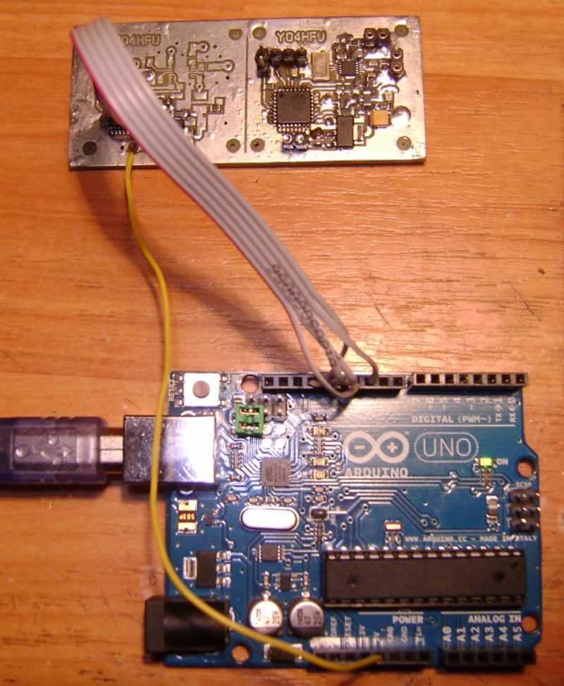
Reconnect USB cable to Arduino UNO. Open Arduino IDE, Tools/Serial Monitor at 115200 baud. Arduino UNO start to communicate with Atmega328:
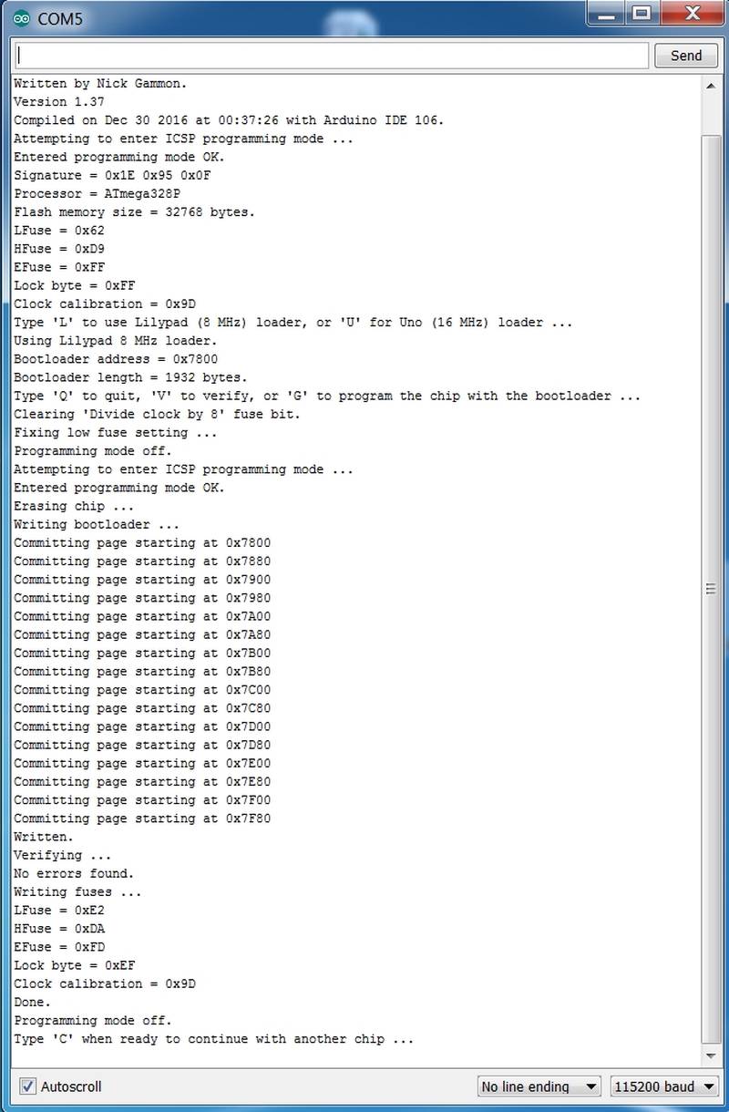
Type "L" and press "SEND". "L" command choose the Bootloader for 8MHz internal oscillator (LilyPad Arduino). Send "G" to start bootloader upload. Succesfully sequence screenshot.
Atmega328 is ready for play...Disconnect USB cable and all wires. Arduino UNO is not longer required.
2. Si5351 I2C address identification
Because Si5351 sometimes don't has default I2C address 0x60, is a good opportunity to check this. My Si5351A has address 0x62 (Farnell supplier). See also I2C Address Scanner page. Atmega328 has the bootloader, so we don't need any additional Arduino Board. Our PCB will be equivalent to LilyPad Arduino Atmega328.
Connect Si5351 board to USB using UART-USB adapter, PL2303 is often used (do not forget about PL2303 Windows driver).
Open "I2C address scanner sketch". Go to Tools/Board and select LilyPad Arduino w/ Atmega328. After that, check Serial Port/Com X, select COM port emulated by PL2303 interface.
Upload the sketch. Open Tools/Serial Monitor at 9600 baud. Si5351 address will be displayed, 0x62 in my case.
3. Atmega328 Software for Si5351 control
Last step is to upload Si5351 sketch written by NT7S Jason Milldrum. Download Si5351A Sketch, do not unzip. Open Sketch/Import library/Add library and select Si5351 zip file. Close Arduino IDE.
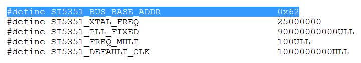
If Si5351 address isn't 0x62, open C:\Users\xxx\Documents\Arduino\libraries\Si5351Arduino-master\src folder (check File/Preferences/Sketchbook location). Use Notepad and edit Si5351 H file (12KB). Change value of #define SI5351_BUS_BASE_ADDR using I2C address found above. Save the modifications.
Restart Arduino IDE and open File/Examples/Si5351 Arduino-master/Si5351Example.
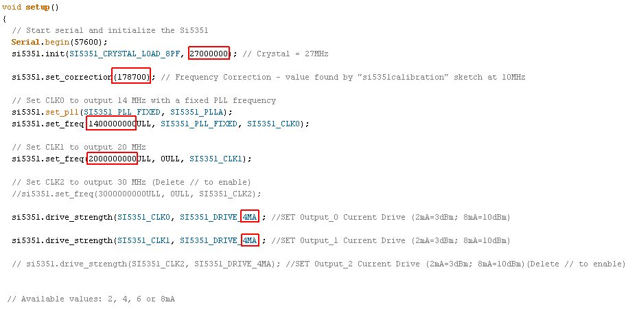
Set desired frequency generated by Si5351 PLL. CLK_0 and CLK_1 frequency in Hz x 100. CLK_2 is not supported by my PCB.
Other options: output current 2, 4, 6 or 8mA; reference crystal 25000000 or 27000000 Hz; Frequency Correction - about this, we speak below.
Note: Frequencies are indicated in units of 0.01 Hz. Therefore, if you prefer to work in 1 Hz increments in your own code, simply multiply each frequency passed to the library by 100ULL. Crystal frequency is set in Hz, without x100 multiplication.
Output level across 50 ohms resistor: 2mA= 0,770V; 4mA=1,43V; 6mA=1,86V and 8mA=2,18V. All values measured at 14MHz using the oscilloscope.
Upload the sketch.
Connect a frequency counter, oscilloscope or listen Si5351 output. Output frequency will be very close, accuracy depends on the reference quartz used.
Note: Si5351 can be factory programmed. Non Volatile Memory is One Time Programmed, which can store a custom user configuration at power-up. Without any I2C control, Si5351 generate CLK_0=50MHz and CLK_1=25MHz (Farnell Suplier). That means no I2C communication between Atmega328-Si5351 or wrong I2C address...
Frequency Calibration:
If its necessary, frequency correction must to be applied. My Si5351 frequency was too high, correction used 1,787KHz at 10MHz.
Open again Si5351Example sketch, set CLK_0 to 1000000000 (10MHz). Upload.
Connect a accurate frequency counter to CLK_0 output pin 10.
Correction factor: (Output frequency Hz - 10000000Hz) x 100. Example: (10001787Hz - 10000000Hz) x100 =178700
Note: if output frequency is less than 10MHz, use negative value of correction, example -178700. Same calibration procedure can be made with "si5351calibration" sketch using Serial Monitor at 57600 baud.
Replace value of si5351.set_correction(0) with si5351.set_correction(178700). Set desired frequencies to CLK_0 and CLK_1. Upload.
PLL Si5351A Completed!!!
Update 09.01.2016
During several tests, was not possible to use CLK_0 for 144MHz. The malfunction can be solved:

Example 144MHz: "si5351.set_freq (14400000000ULL, 0ULL, SI5351_CLK0)".
"si5351.set_pll()" no need to be changed.
![]()
![]() Bootloader sketch for Arduino UNO (http://www.gammon.com.au/breadboard)
Bootloader sketch for Arduino UNO (http://www.gammon.com.au/breadboard)
![]() Si5351A sketch for Atmega328 (NT7S Jason Milldrum)
Si5351A sketch for Atmega328 (NT7S Jason Milldrum)
![]() I2C Address Scanner sketch for Atmega328 (http://playground.arduino.cc/Main/I2cScanner)
I2C Address Scanner sketch for Atmega328 (http://playground.arduino.cc/Main/I2cScanner)
![]() PLL Si5351A/Atmega328 Schematic
PLL Si5351A/Atmega328 Schematic
![]() PLL Si5351A/Atmega328 PCB (Sprint Layout 6 and .pdf top)
PLL Si5351A/Atmega328 PCB (Sprint Layout 6 and .pdf top)
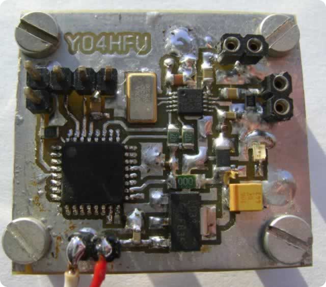
![]() Si5351A Board during development
Si5351A Board during development
![]() Si5351A output at 1,216MHz and 50 ohms resistor
Si5351A output at 1,216MHz and 50 ohms resistor
![]() ClockBuilder Desktop - Si5351 (v6.5) - to find registers values
ClockBuilder Desktop - Si5351 (v6.5) - to find registers values