
| The bandpass filters used in this receiver are based on the article in the September/October 2000 issue of QEX called "Narrow Band-Pass Filters for HF", by William Sabin, W0IYH. These filters are implemented using fewer parts than other double-tuned NBPFs and they work very well. |
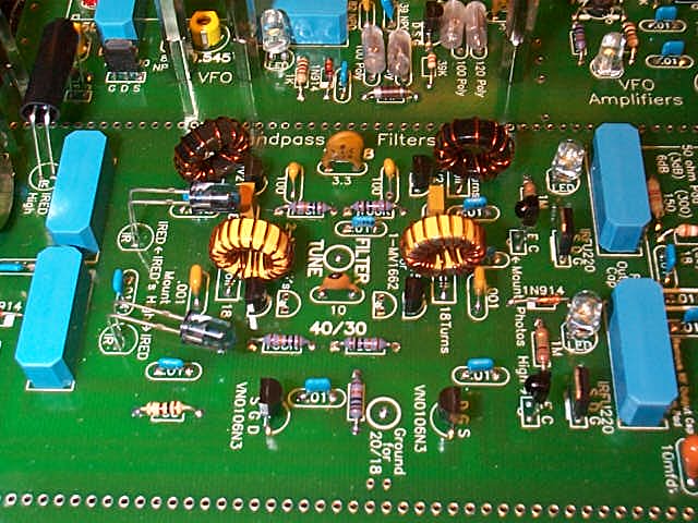
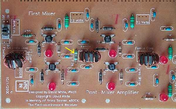
The most amazing item about these filters is their low loss. When set up with the design values, sometimes I have had trouble measuring the loss. With only 1-2db loss, these filters beat anything else I have built. I was able to eliminate three trimmers from each filter with Sabin's design. The filter values are obtained on the internet by downloading NBPF.ZIP from the ARRL site at http://www.arrl.org/files/qex/. Everything you need to know is in the downloadable .zip file. This kit uses the top coupled filters. Design Process for the Receiver FiltersThe values for the toroids were first determined by averaging the value of each set. For example, the value for 40 meters is 1.75uH and the value for 30 is 1.06uH. The value used for that filter was approximately 1.4uH. A MV1662 varicap was able to hit both bands without any additional capacitance. On the 20/17 filter, a MV2115 was used with 100pf parallel capacitance. After these filters were designed, a core change in the mixer increased the gain of the mixer. As a result, the filters needed more selectivity to cope with the additional gain in the mixer. Raising the value of inductance would raise the "Q" the filters. The inductance of the 40/30 filters was raised to 3.450 - 3.550uH (29 turns of #22 wire on a T50-6). This filter tunes 4.4 MHz to 14.5 MHz. The 100pf capacitor was taken out of the 20/17 filter and the inductance raised to 1.0uH (15 turns of #22 wire on a T50-6). The 20/17 filter tunes 11.6 MHz to 20 MHz. Raising the Q with the increased inductance did not impact losses. Tuning is sharp and selective. If there is still feedthrough from other interference, the Gain Adjust on the VFO amplifier is lowered. Lowering the drive to the mixer decreases its gain, effectively increasing the performance of the bandpass filters. LED IndicatorsThe picture above shows the bandpass filter with both LEDs on. This was due to the lighting needed to take the shot, but normally only one of the LEDs is on indicating which filter is active. The limiting resistor for the LEDs is the coil resistance of the relays (500 ohms). There is also a small loss through the IRFU220s, which turn on the relays when gate voltage nears 4 volts as a result of IR energy hitting the IR diodes. The IR LEDs can be seen in front of the output relays. (Directly above the relays at the bottom of the picture.) The switching circuit (two VN106N3's) supplies power to the output relays (the bottom relays in the picture directly above). The IR LEDs are in the ground circuit of the output relays, and they turn on the input relay through the photodiodes, on the opposite side of the bandpass filters. The 20 meter output relay has two IR LEDs, one turns on the input relay and the other turns on the 10.455 VFO relay/LED through a photodiode. The 10.455 relay turns on only when the 10.545 relay is on (when the 3.547 MHz crystal filter is on). The LED on the 20/17 side will flash once when turned on. The reason is two IR LEDs are turned on at once when the 20 meter bandpass filter is turned on. Switching CircuitWhen power is applied to the receiver, 40 meters is received (switches not installed or turned off). The 40/30 bandpass filter and the 3.547 MHz crystal filter are turned on. The VFO 10.545 relay is switched on by the IR LED from the 3.547 MHz crystal filter. VN106N3s and IRFU220s are used in the switching circuits. Only one wire, grounded by an SPST switch, is needed to switch the bandpass and crystal filters. The VFO is switched by the action of both filters through IR circuits. The IR devices are used as simple on-off switches. Infrared energy sent to an IR device turns it on, raising the gate voltage (to 4 volts) of an IRFU220 to turn on a relay (VFO or Bandpass Filter) or a crystal (Crystal Oscillator). When the receiver is turned on, the dual VN106N3 circuit turns on the 40/30 bandpass filter. To change to the 20/17 bandpass filter, the "Ground for 20/17" pad is grounded with an SPST switch. Second, the 3.547 MHz crystal filter is turned on by the VN106N3s which turns on the 10.545 VFO relay with its IRED in the two-LED input circuit. By grounding the "Ground for 30/17" pad with an SPST switch, the 10.545 VFO relay is turned off. The 3.547 crystal at the crystal filter is turned on by the IRED at the input circuit to the 4.000 crystal filter. BG Micro carries the photo parts that are used in this receiver (IRED Part #LED1067). The IREDs that are used in the kit (LTE-4208C) are special high output types. This IRED was essential for the design of this receiver. All the other IREDs I tested didn't even come close to the LTE-4208C. Tuning the Bandpass FiltersTuning of the bandpass filters is done by a 100K panel mounted variable resistor. There is no missing the band noise when tuning, except on 17 meters, which can be pretty quiet. A label showing the approximate location where the ham bands are tuned is at "Labels for the Receiver Dials."When popping and instability are heard when tuning the pot, turn down the "Gain Adjust" pot at the first VFO amplifier to reduce mixer gain, and the spurious responses will disappear. The fix for the popping is to place a 2.2K resistor between the ends of the center bifilar coil in the mixer/amp combination on Board 1. The 2.2K resistor is incorporated into the Rev 2 boards as shown below. |
|
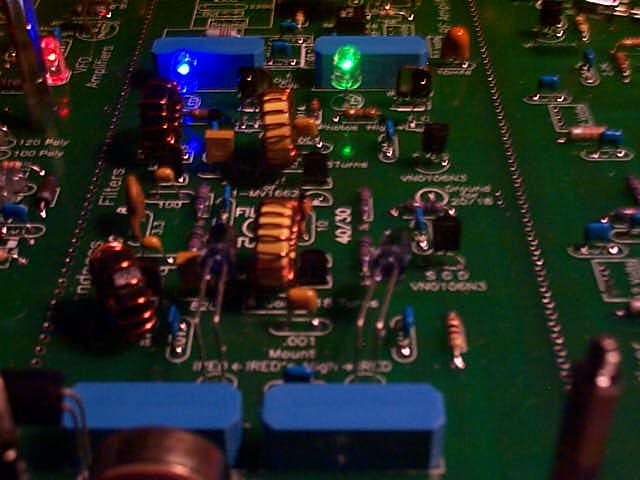
If you have the Salmon Pink boards (first run of boards), the 2.2K resistor should be tack soldered to the ends of the center bifilar coil underneath the board. The placement of this resistor is illustrated in the instructions for the earlier boards (elrbuild13.htm). Another fix is to ground the 100K potentiometer case. The ungrounded case can pick up stray RF from the bandpass filters and any RF floating around the receiver. A bare piece of hook up wire is soldered to the case and the nearest ground connection (elrbuild12.htm). Termination of the Filters and GainReceiver gurus will notice that the filter is terminated at 50 ohms at the input, but the output has a very high termination value. When this can be done, it is a benefit in lowering loss in the filter and keeping signal levels high. I quote Solid State Design, page 240, "Post Mixer Amplifier": "...In some cases, it is desirable that a filter not be terminated at both ends. One example might be the input to a receiver where a double-tuned circuit is used to drive the input of an FET mixer or amplifier. The lack of termination leads to higher voltage transformation ratios, increasing gain of the FET circuit." The gain of the Mixer/Amplifier is 14dB to 19dB, depending on the band used. Remember, this receiver was designed to be used with an indoor antenna (antennas used for testing were Hamsticks inside a bedroom window), and outside antennas can overload the receiver. There are two ways to adjust the receiver for outdoor antennas. One is to turn down the "Gain Adjust" at the first VFO amplifier to lower the gain of the mixer to compensate for the higher signal levels. The second fix is to bypass the RF amplifier. An unmarked hole is provided at the input of the bandpass filter for the modification. Two .01 capacitors are removed and a piece of hookup wire is connected between the output of the TV and FM input filter and the input to the bandpass filters. See the picture below. |
|
These modifications were made on the 40/30 bandpass filters to help reception with a 121 foot long wire antenna. The problem was 39 meter broadcast stations were leaking through the filter due to the high level of signals coming from the long wire antenna and a high intensity noise level. If you live in a high level noise situation (poor city environment) these modifications will help considerably in getting the noise level down to a level that will make the receiver less tiring for listening. The coils in the filter were lowered to 21 turns, the original design values for the filter from the Sabin article. Then the coupling capacitor was lowered to 2.5pf to tighten the bandpass of the filter. The result is higher losses in the filter with the tighter bandwidth. The noise level was lowered to barely any S-Meter indication and the 39 meter broadcast stations virtually disappeared. The bandpass was now about 200 to 300 kHz with a very sharp peak on the dial. Note that the peak for the 40 meter band is at the same place on the dial as the 20 meter band and the 30 meter band moved to where the 40 meter band used to peak. The peaks are easy to find with the band noise. If the coupling cap between the sections was left at 10pf, the loss through the filter was very low. The bandwith was 500 kHz. This value was used to measure the MDS figures on the receiver which came to -141dBm, a very respectable value. The 21 turn coils and 10pf coupling cap can be used with dipoles and verticals in a low noise environment for maximum sensitivity. |

|
An RF Gain Control can be implemented with a 400 to 500 pf varicap, a few resistors and a variable potentiometer. The value of the varicap is not critical as long it is of a high enough value to make a difference between its low value and high value capacitance. Any of the Hyper-abrupt varicaps used for AM radios will work. (MVAM series, MMBV series, MV16XX series) The RF Gain can be used in conjunction with the coupling capacitor in the "Narrowing the Bandpass Width" section to adjust your antenna farm to varying band conditions for the best reception. |
|
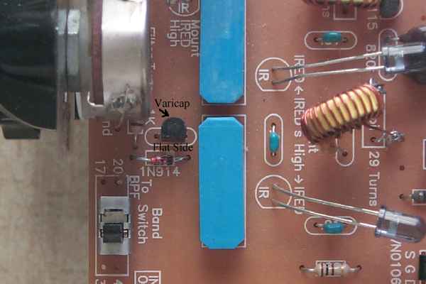
The .01 capacitor next to the 1N914 diode is removed from the board and the varicap is mounted in its footprint. The varicap is placed with its cathode toward the bandpass filter. There is another coupling cap on the cathode side so voltage can be applied in this position to vary the varicap capacitance. See the picture above noting the position of the flat side of the varicap. The anode of the varicap is grounded through the 5 turn winding at the input transformer of the mixer. |
|
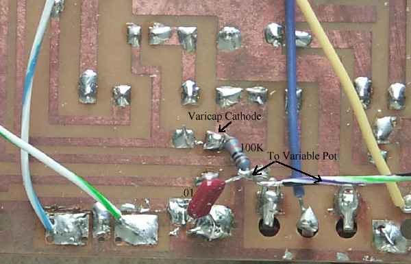
A 100K resistor and a .01 capacitor are mounted as close to the varicap as possible. One end of the 100K resistor is mounted at the cathode of the varicap, the lead closest to the bandpass filter relays. Next, one lead of a .01 capacitor is soldered to the ground plane of the PCB. Then both of the unsoldered leads of the resistor and the capacitor are soldered together. This junction is soldered to a wire that goes to the center terminal of a 50K or 100K potentiometer. The pot is mounted on the front panel of the receiver or to a piece of scrap PCB that mounts it at the front of the bottom board for easy access. A 1K resistor is soldered to each end terminal of the potentiometer, one 1K resistor going to a 12 Volt connection and the other 1K going to a ground connection. To make the control go from low gain to high gain as the knob is turned clockwise, solder the resistor on the left terminal to ground and the resistor on the right terminal to 12 Volts. |
|
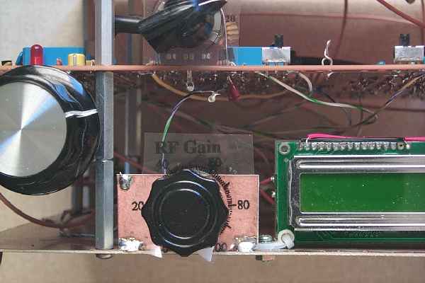
Picture showing RF Gain Control mounted on the bottom plate with a piece of scrap PCB. |
References"Narrow Band-Pass Filters for HF", by William Sabin, W0IYH, September/October 2000, QEX "Double Tuned Circuits with Mixed Terminations - A Case Study.", Wes Hayward, W7ZOI, April 20, 2008. On the EMRFD Yahoo Groups site. |
Board 1 || VFO || TV & FM, BC Filters || RF Amplifier || Bandpass Filters || First Mixer & Amplifier || Crystal Filter
Send E-Mail || Amateur Radio Receivers || Electroluminescent Receiver
