
|
In the April 1999 issue of QRP Quarterly, Chris Trask, N7ZWY, states in his article, "LC Oscillators - A Brief History", (speaking of the Vackar Oscillator) "The last of the significant improvements in LC oscillators was developed at the same time as the Gouriet circuit was being devised, ...Created by Jiri Vackar in Czechoslovakia, the stability is improved by placing a variable capacitor... The same circuit, also known as a Tesla Oscillator, was developed independently in Italy by O. Landini." So I decided to use the name Tesla Oscillator, in honor of my favorite inventor. |
|
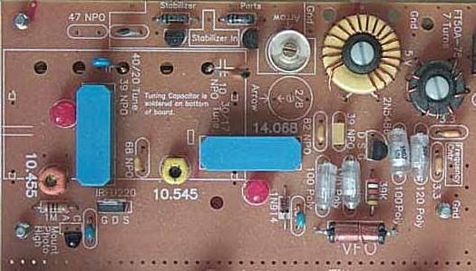
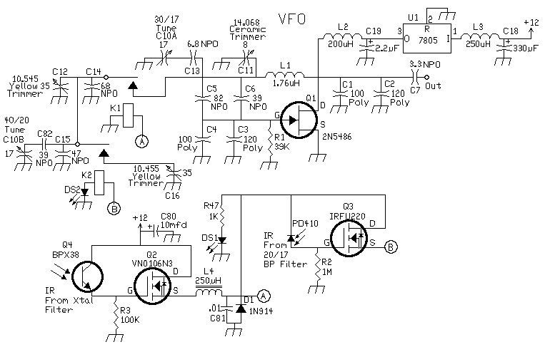
The three VFO frequencies are 14.068 MHz, 10.545 MHz, and 10.455 MHz. The relays are switched by IR devices, using the circuit at the bottom.
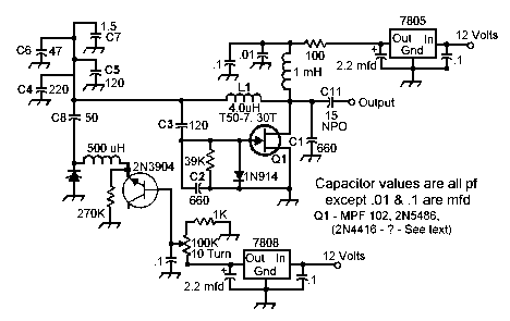
I designed the basic oscillator for 12 MHz. This determined the inductance for the coil and the capacitor values off the Drain and Gate of the 2N5486. The capacitor values were 220pf (split between two values - 100pf & 120pf poly caps). The coil is 18 turns on a T68-6. The feedback capacitor value (120pf) is split between 39pf (C5) and 82pf (C6) NPOs. The oscillator was set at 14 MHz by removing capacitance between the coil to ground. The other places, off the drain and gate, had some, but not enough effect on the frequency to use. Relays are used to add additional capacitance between the coil and ground to reach 10.545 MHz and 10.455 MHz. IR switching is used to switch the relays. The range of the VFO is about 9 MHz to above 15 MHz with the 120pf feedback capacitor value and 220pf on the drain and gate. Extending the range is done by changing the value of the feedback capacitor. Lower the feedback capacitor value for higher frequencies and raise the value for lower VFO frequencies. A "Huff and Puff" frequency stabilizer is available as an option for increasing the stability of the VFO. For information on the "Huff and Puff" frequency stabilizer, check out "'Huff and Puff' Frequency Stabilizer". Important RF Choke InformationCaution: When building and using this circuit you can blow the 2N5486 in a split second by shorting any of the capacitors off the coil to ground. Shorting the coil to ground on the opposite side of 12 Volts generates a spike of voltage that instantly blows the gate of the FET. This is very similar to what is used in automobile ignition circuits with a point type distributor. Do not use a molded choke in a Vacker VFO circuit. A hand wound FT37-43 or FT50-43 (20 turns) or the ones in the kit, FT50A-75 (7 turns) with #24 wire, will hold its choking ability if you momentarily short the coil. The molded chokes use very fine wire. Even the shortest full voltage spike will blow their choking ability, but not necessarily their ability to pass DC. The RF choke is a drift contributing part. Ferrite material absorbs heat quickly, way ahead of the toroid or capacitors in the VFO. It is important to cover the choke with melted candle wax (or some other suitable material) to slow the temperature change to approximately the same rate of the poly caps to enhance frequency and mechanical stability. Two values were tried on a FT50A-75, a 16 turn (1 mHy), and a 7 turn, (220uH) for the RF choke. The 7 turn choke moved less in value with temperature changes. |
|
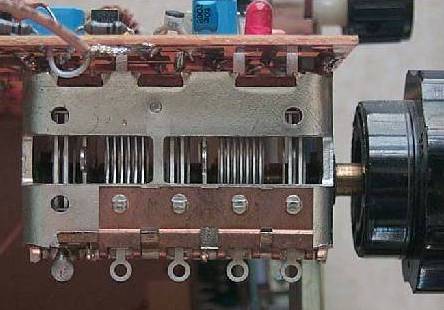
The photo above shows the tuning capacitor soldered to the bottom of the printed circuit board. Holes are in the PCB above the tuning capacitor tabs, so they can be easily soldered. The tuning capacitor is a five section variable, 30-200-30-86-25, front to back. Soldering the tuning capacitor on the board allows a quick setup and stable VFO. Soldering the main tuning capacitor on the PCB board resolves the hardest part of building a receiver: mounting the main tuning capacitor. The two end sections of the tuning capacitor are used: the front one for 40 and 20 meters and the rear one for 30 and 17 meters. The front section tunes the 10.545 MHz (40 meters) and 10.455 MHz (20 meters) frequencies. Relays on the top side determine which frequency is running, switched by IR devices located at the Crystal Filter and the 20/17 Bandpass Filter. The rear section of the main tuning capacitor tunes the 14.068 MHz frequency used for 30 and 17 meters. The coupling capacitor sets the bandwidth. A 6.8pf NPO capacitor gives 100 kHz bandwidth, 14.068 MHz to ~14.168 MHz. With a 10pf NPO cap, the bandwidth will include WWV as well as the amateur bands, 14.100 MHz to ~14.200 MHz. Modifying BandwidthsThe coupling capacitors are in series with the tuning capacitor, so raising the coupling cap value raises the effective capacitance of the tuning capacitor, giving a wider bandspread. For absolute maximum bandspread, the coupling cap could be shorted and all the capacitance of the main tuning cap would be in the circuit. Conversely, lowering the coupling capacitor lowers the effective capacitance of the main tuning cap, which shortens the bandwidth of the VFO. 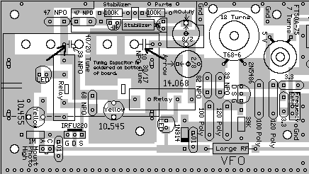 The 39pf NPO capacitor is used for the 40 and 20 meter bands (10.545 MHz and 10.455 MHz). The 10pf NPO (or 6.8pf NPO) capacitor is used for the 30 and 17 meter bands (14.000 MHz). For setting different bandwidth values, experiment with both the coupling capacitor and adding/changing sections of the main tuning capacitor. Do not change the 100pf and 120pf poly capacitors unless major frequency changes are being made to the VFO (way outside the 9 MHz to 15 MHz range of the VFO). The poly caps provide compensation for the drift in the FET and the toroid. 14 MHz VFO SectionChanging the 14 MHz VFO frequency will also effect the 10 MHz section of the VFO. The 10 MHz section adds capacitance to the 14 MHz section to lower the frequency to the 10 MHz values. So raising or lowering the 14 MHz section will raise or lower the 10 MHz frequencies. When modifying the 14 MHz VFO section, after changing the coupling capacitor or main tuning capacitor sections, if the 2/8 ceramic trimmer does not reach the new frequency, change the number of turns on the VFO toroid or change the value of feedback capacitors. One is a blue capacitor (39pf NPO) and the other is an orange capacitor located right next to the blue one (82pf NPO). The feedback capacitors must be high quality NPOs for excellent stability. The feedback capacitors were found to be the most critical in achieving stability with this VFO. Since the bandwidth of the 30 and 17 Meter bands are not very wide, the entire bands are covered with the stock capacitors and no modifications are normally needed. 10 MHz VFO SectionWhen modifying the 10 MHz section, the 39pf NPO capacitor is used to set the bandwidth along with adding sections of the tuning capacitor. The stock bandwidth for this section is approximately 130 kHz, which is easy to tune CW or SSB with a large knob on the tuning capacitor. If the entire bandwidth for 40 and 20 meters is desired, consider adding a homemade or commercial reduction dial for easier tuning. For extending the bandwidth to the entire band, change the 39 NPO capacitor to 47pf NPO and tie the center section and the one just forward (8 rotor plates and 6 stator plates) together with a jumper. See picture below: 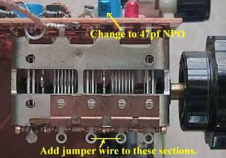 The resulting bandwidths will be 358 kHz for 40 Meters and 332 kHz for 20 Meters. After making the modifications, first set the 40 meter section (10.545 yellow trimmer) to 10.545 MHz or less (to account for drift from temperature changes so you will always be able to reach 7.000 MHz). Then adjust the 20 meter section (10.455 yellow trimmer) to 10.455 MHz or less. Relay and Infra-red OperationWhen the 3.547 crystal filter and 40 meter bandpass filter is selected, the LED next to the 10.545 relay lights and the VFO runs at 10.545 and up. This will cover the 40 meter CW band with a bandwidth of about 100 kHz. The yellow trimmer next to the lettering 10.545 sets the VFO to 10.545 MHz. The coupling capacitor to the main tuning capacitor is 39pf (blue capacitor on the top left of the picture). The relay on the left is activated by switching the bandpass filter to 20 meters, moving the VFO to 10.455 MHz. Both VFO LEDs will be on. The yellow trimmer next to the lettering 10.455 adjusts the VFO to 10.455 MHz. Bandwidth is 100 kHz. In the pictures explaining the IR switching, a black tube is seen at two places, one that goes across from the crystal filters to the middle of the VFO amps and one at the bottom of the 20 meter bandpass filter. The reason is to keep the current through the relays constant. Magnetism from the relays affects the VFO frequency. Changing light levels can move the VFO frequency up to 300Hz. The black tubes make the VFO insensitive to ambient light levels. When the IR receivers are getting some light from a shop light, either incandescent or fluorescent, it will cause a 60 cycle raspy sound on the CW notes. Please note this when you first fire up the receiver without the black tubes installed. This is modulation from your work light on the VFO IR receivers. The IR receiver between the VFO amplifiers is a photo transistor and the one at the bottom of the VFO is a photo diode. |
ReferencesSome good articles on the Vackar VFO are the following: "Miniature Solid-State Variable-Frequency Oscillator" (This miniature circuit board can be used for either the Seiler or Vackar oscillator circuits, including the Buffer-amplifier and emitter follower.), by Donald R. Nesbitt, K4BGF, Ham Radio, December 1971, pp 9-11. "A VFO for Solid-State Transmitters" (Tired of being rockbound? Here's a neat VFO featuring the Vackar oscillator.), by C.E. Galbreth, W3QBO, Ham Radio, August 1970, pp 37-40. "The Vackar High-Stability L-C Oscillator", by Floyd E. Carter, K6BSU, CQ, June 1994, pp 26-29. A circuit that uses a MOSFET for the active device. This is a very interesting circuit, for using the MOSFET with Gate 2 biased properly is supposed to enhance VFO stability. This is not mentioned in the article. Must reading for serious Vackar users. "Meet the Remarkable but little-known Vackar VFO", by Floyd Carter, QST, September 1978, pp 15. "Voltage Controlled Oscillator Uses Ceramic Resonators", by Albert D. Helfrick, K2BLA, Ham Radio, June 1985, pp 18-26. The ceramic resonator offers a wider tuning range than a crystal with rock solid stability. |
Send E-Mail || Amateur Radio Receivers || Electroluminescent Receiver
