|
|
||
01/02/07 |
 
|
"W4XE Repeater Tech page ©"
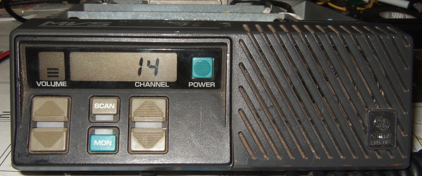
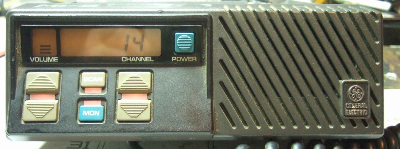
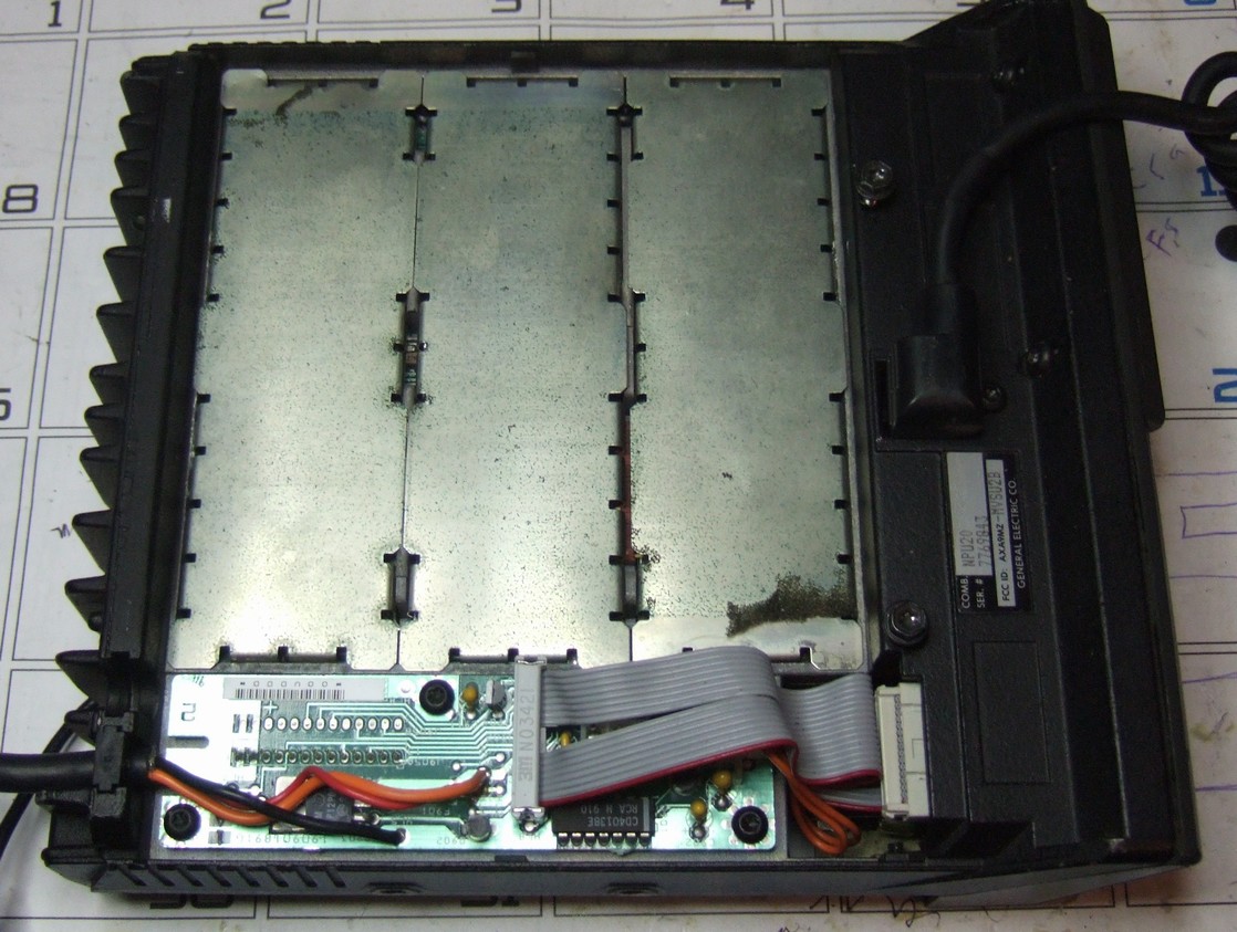
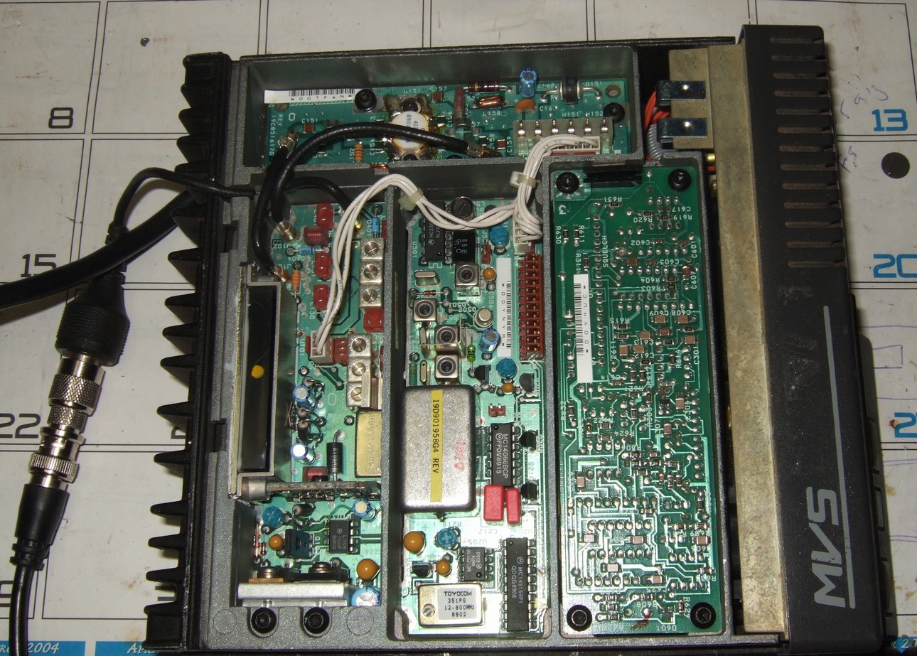
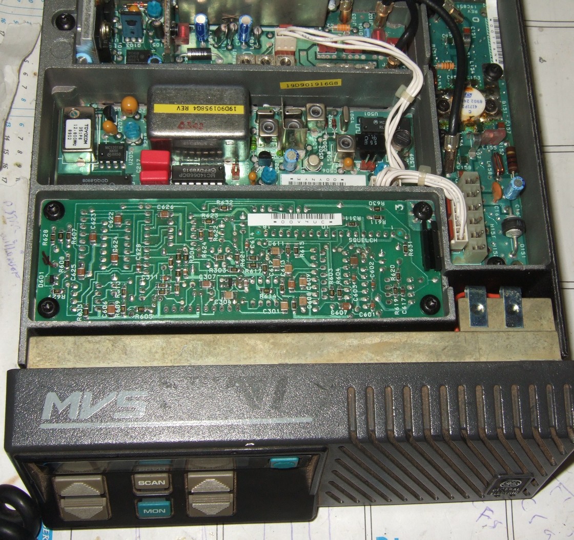
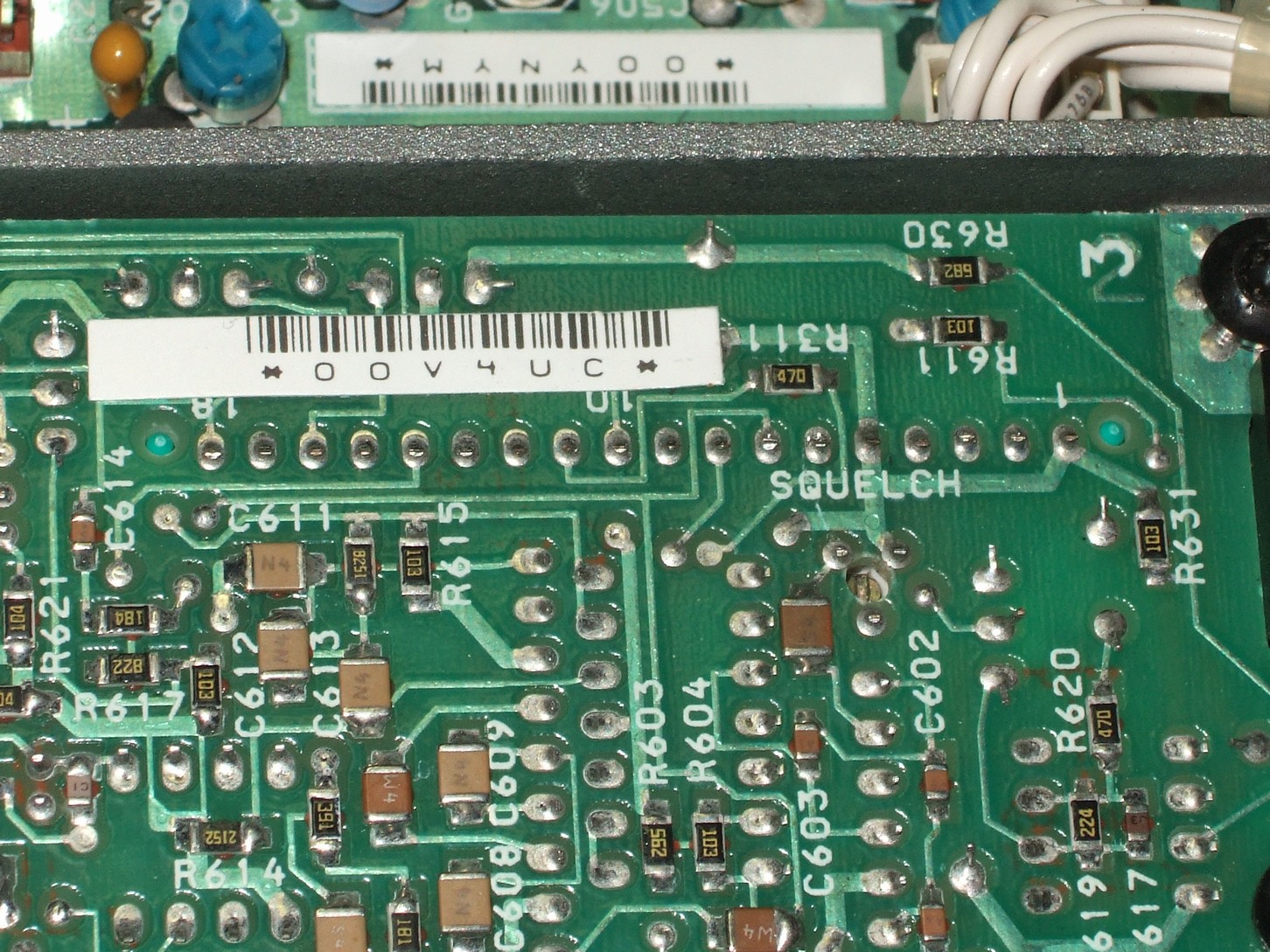
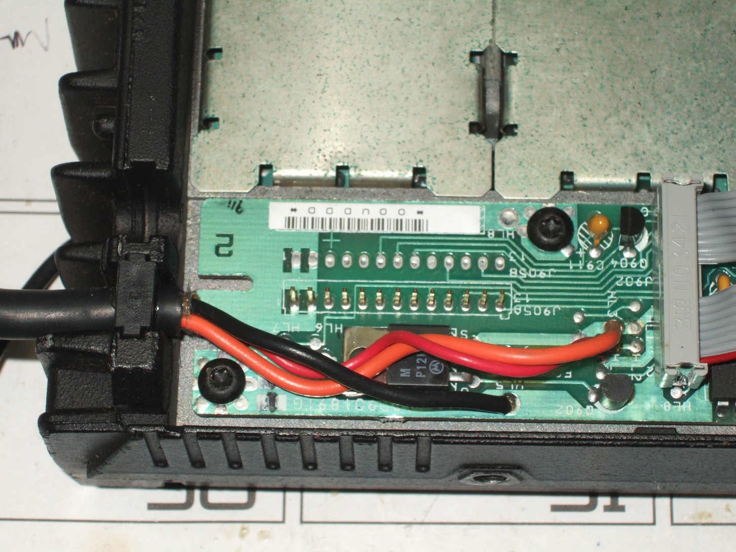
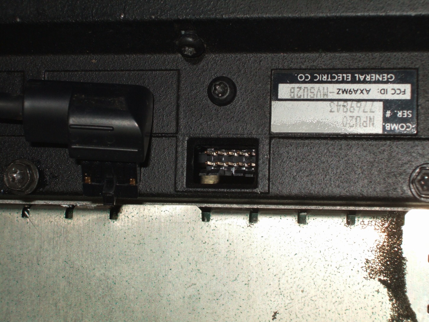
After working with the GE Phoenix SX, the next radio I was curious about was the newer GE MVS radio. This is an under dash VHF or UHF mobile radio with 40W or 25 W output power. There are 2 channel and 16 channel versions. They are synthesized with programmable PL or DPL. I do not know of a modification to get 16 channels from a 2 channel radio, so buyers beware if you need 16 channels. A couple of things to note about these radios. First they are serially programmed using an old DOS based computer. You have to have the GE software to do this and a serial conversion cable. The cable is available from: Bill - WA2PVV [email protected]. Please don't call me about the software. You plug the cable into the microphone jack for programming the radio. The radio has an 8 pin EEPROM which I assume holds the channel/pl info. I haven't seen anyone attempt to decode it's contents. Let me know if you do. The radio works a little different than a phoenix radio during complete power removal from the radio. For a Phoenix radio if you totally remove power from the radio, it will reset to channel 1 upon boot up. This can be nice if you plan on bumping channels for a semi frequency-agile remote base. With an external power relay you can reset the radio to channel 1. In this way you don't have to play Russian Roulette about where you are starting from. For the MVS, the radio remembers which channel it was on and returns to that channel when power is restored. This is bad for the reset trick to channel one. However it is good in another aspect. If you use a Phoenix and normally want the radio 99% of the time on a dedicated link frequency then you HAVE to put that into channel 1 mode A or B. Else if you lose power at the site, the link radio will not be on the right frequency after power is restored. The MVS doesn't have this problem and you can be certain the radio will be on the channel you left it on after a power failure. As noted elsewhere on the web, Ray's site if I remember right, the Phoenix radio had a sore point in its design. The front volume control along with its on/off switch will fail. I've seen radios retrofitted with new volume pots and power switches so I can attest to that fact. Since the MVS was newer, it has a push button on/off along with a digital volume pot control. The volume is an up/down push button and the LCD shows the level of volume on a bar graph. One would guess the GE engineers were told to fix the Phoenix volume control issue in the next radio. There are a few club repeater websites that show an MVS used as a remote base for a repeater or using two MVS radios as a repeater. But nothing I could find on the web about details for wiring these up for use as remote base radios for repeater. Here is a document of some of my findings for hooking up the radio for use as a remote base. Click here to download the PDF file The microphone connector provides a lot of the access points: RX audio, COS, TX audio and PTT. However, the receiver audio on this connector is up to 3W and varies with the volume control. I dislike using an audio source for a repeater or remote base that varies with a user accessible pot that can be bumped or tweaked by anyone. Been there, done that and it is not good. There are some more interesting access points inside the radio on J905 and J703. The standard top of the volume pot volume-squelch-hi discriminator audio is available. There is also a point to tap the output of a de-emphasis and high pass audio filter. The amplitude is a little hot, so you might want to attenuate it with a pot before sending this to your repeater controller. It is always a good idea to remove a users PL tone. If your remote base radio is accessing a distant repeater with one PL tone and your main repeater is on a different tone, you can get motor boat beating of those two low frequency signals. The nice thing about the MVS unlike a lot of receiver designs you see is that this signal is BEFORE the volume pot control or power audio circuit. The other point needed for any remote base or repeater project is the receivers activity indicator. This is usually called COS, Carrier operated Squelch. The MVS provides several locations for this signal. See the documentation above. All of them provide basically the same information. With AUDIOMUTE* and no RX signal present the signal will be close to zero volts DC. With an RX signal the output will be close to 5.0 VDC, a TTL level logic signal. If the channel is programmed for carrier squelch only, this signal will go High (5 VDC) on any signal on the channel. If the channel is programmed for Channel Guard (PL/DPL/CTCSS) required then only a signal with the proper tone(s) will unmute the radio and cause AUDIOMUTE* to go high. For a channel guarded memory this in effect becomes COS+PL, or COS AND PL. It requires both to be TRUE for the signal AUDIOMUTE to go ACTIVE HIGH. If you require a separate COS detect only no matter what the PL is doing, there is a classic GE signal called CAS or Carrier activated Squelch on J703. It will go active high on any signal present at the receiver. Having separate COS and PL detection signals is handy if you want to remotely turn off any PL requirements in a repeater application. A note of warning! The COS signal(s) you tap off of in the radio are TTL logic signals used by the internal microprocessor of the radio. They do not have a high drive level that may be required by your external repeater controller. Hooking up the controller may damage your radio permanently or at least cause it to malfunction whenever you load the line down. I would highly recommend you feed the AUDIOMUTE signal into a transistor buffer. Tie one end of a 10K ohm resistor to AUDIOMUTE. Tie the other end of the resistor to the base of a 2N3904 transistor. Tie the emitter lead of the transistor to Ground. Tie the collector of the transistor to your repeater controllers COS for the remote base. Upon a signal detect, the collector will pull down to ground for an ACTIVE LOW COS detect. Your controller may need you to pull this collector signal line up with a 1K resistor to +12VDC so that a voltage is present to indicate NO activity. If the controller needs an active High COS, just add another transistor after this one to invert the signal. Commercial radios normally have some form of Microphone 'hang up' system. If the radio is on a Channel Guard (PL) channel and the microphone is placed in its holder, the user won't hear any traffic on the frequency if his tone is not being used. This may be the case in a 'community' repeater where many businesses use a common repeater, but each uses a different PL tone. Whenever the user removes his mike to talk, the radio goes to Carrier only mode. In this way if the channel is being used he will hear the traffic and hopefully wait until the frequency is clear before talking. The MVS uses a magnetic reed switch inside the microphone. The microphone holder has a permanent magnet so that when the mike is in the holder the switch is activated. For ham use, I open the mike (2 screws on the back) and cut one lead off the magnetic reed switch. In this way the mike doesn't have to be in a special hanger to activate the PL requirement. Instead you can use the front panel 'MONITOR' button to open the radio up. A mobile radio is designed for a low duty cycle transmit. For repeater or remote base applications this will stress the radio's RF final PA. The heat sink assembly is not big enough to keep the transmitter cool and the radio will overheat. You must always turn down the power output and provide external cooling. Remember to derate the mobile output power if you are going to use them in a repeater application and run a BIG fan!
GE MVS LINKS: http://www.rocler.qc.ca/burt/mvs_u_1.html MVS packet testing http://www.rayvaughan.com/kpc3_to_mvs.htm Ray's website mentions some wiring of these up to a packet controller. http://www.hallelectronics.com/getech/np1.htm Manual publication #'s http://www.hallelectronics.com/getech/np2.htm Model #'s http://www.brinkleyelectronics.com/crossref/ge/mvs/mvs.htm MVS model number decoder wheel chart. http://www.k3jls.com/mvs.htm Interesting website for converting the front panel to a new LCD panel and computer control of the synthesizer for a more 'ham friendly' radio. http://www.repeater-builder.com/ge/lbi-master-list.html An excellent website that has gigabytes of GE documentation. You'll find the manuals for the MVS on there. http://www.w5kgt.com/ares.html A very impressive 100' mobile emergency tower with a uhf and vhf repeater as well as a crossband unit. One of the repeaters is made out of two MVS radios and the other out of two Phoenix radios. 73's Ralph W4XE 01/02/2007
|
This site was last updated 01/02/07