Kenwood TM742

The Kenwood TM742 is an excellent radio for use with either RotorHunter or VectorFox as it can be readily modified to provide signal meter outputs for each band. The TM742 was available in a variety of configurations including 28, 52, 144, 220, 430 and 1290 MHz, depending on the band modules fitted. Kenwood also released the TM942 which is the same as the TM742, but has 1290 MHz fited as standard.

The Kenwood TM742 also has an audio output, via the microphone connector, which is designed for packet operation. This output (called RD in the Kenwood manual) can be used to drive a noise meter circuit. When driving the noise meter circuit it is best to have the RD audio bypass the squelch control. Information on setting the RD function are given here.

Signal meter output.

When using the Kenwood TM742 with either RotorHunter or VectorFox a method of detecting the received signal level is required.
The TM742 uses a FM limiter and detector IC in each module to resolve the FM reception and contert it into audio. One function of this IC is to provide a DC voltage, proportional to the receiver input, to drive the S meter on the front panel. This voltage is present on pin 11 of IC 5 on the 144 MHz module. This voltage changes from about 0.9 Volts with no signal input to about 5.2 Volts at maximum signal. Normally this voltage is fed to the front board inside the radio via pin 10 of CN1.

I have highlighted these connections in green on the circuit diagrams.


Signal meter (SM) output of IC 5
on the 144 MHz band module

Connector CN1 on the 144 MHz band module


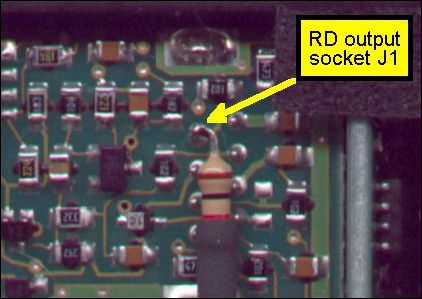
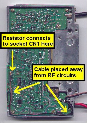
The signal meter voltage is present on pin 10 of CN1 for all of the band modules. As the CN1 connector is in the same place, this method can be used with all modules.
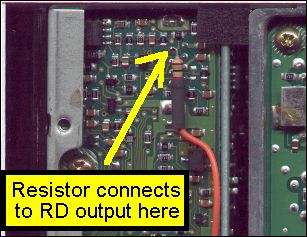
The signal meter (SM) voltage can be accessed from the underside of the board at pin 10 of the CN1 connector. I have added a 1k 1/4 watt resistor in series with the voltage to offer some isolation between the radio and the outside world. You can see where the resistor is soldered in this picture.

After soldering the resistor to pin 10 of CN1 the wire must be routed along the side of the radio away from the RF circuits. If the wire is run near the RF circuits the radio may be damaged when you transmit. There is a small cut out in each of the band modules heatsink. This is where the wires come out. I have used two 3.5mm stereo panel sockets to allow external connections. These sockets have been filed down so they fit in the air holes in the fan assembly. This will restrict the amount of air flowing past the heatsink so you should avoid lengthy transmissions at high power.
Receive audio output
In addition to the signal meter voltages, the RD output can also be brought out onto a socket on the back panel. I make use of one of the 3.5 mm stereo sockets described above. You can see a connection diagram here. The RD output is normally presented on the microphone connector. I have run a wire from this connector to the back of the radio. Again I have included a 1k 1/4 watt resistor to provide some isolation.
The RD output provides audio from the selected band, independent of the volume control, and switched by the squelch contol, if required. This audio can be used to drive the noise meter circuit.


For information on setting the RD output click here.


home page Kenwood TM742 RotorHunter vk3zpf@qsl.net

Copyright 2001 - Peter Fraser - all rights reserved.